
Reciprocating hydraulic pressure intensifiers generate higher pressure from a low-pressure hydraulic power source, helping to conserve energy, cost and space.
By Anders Levinsen, Sales & Marketing Manager, ScanWill
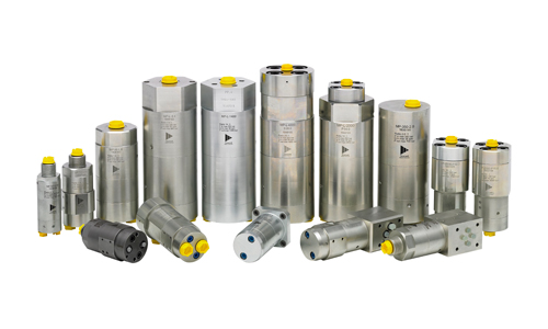
Hydraulic pressure intensifiers from Scan Will are available in many sizes, pressures and for a variety of mounting requirements.
Hydraulic pressure intensifiers, sometimes referred to as hydraulic pressure boosters, generate a higher pressure from a low-pressure hydraulic power source. They always work powered by a pump, which is operating at a set pressure and from this the intensifier simply generates a higher output pressure. They are most commonly used in hydraulic power packs but originally had their beginnings in the workholding industry for use with CNC machines.
How the reciprocating intensifiers work
These devices are based on a differential piston principle, where a larger diameter piston pushes a smaller diameter piston, thus increasing the pressure to a factor equal to the ratio: Larger diameter area divided by smaller diameter area. The outlet pressure will always be proportional to the supplied pressure. The movement of the intensifier pistons is controlled by internal valves, and the piston speed can be as high as 20 Hz when increasing the pressure. At this point the intensifier continuously delivers flow to the high-pressure side. When the end pressure is reached, the piston movement stops. In case of a pressure drop on the high-pressure side, the intensifier will automatically start working to maintain the pressure.
Design and pressures
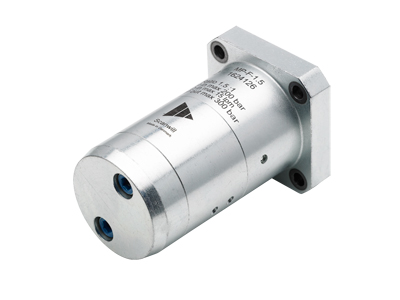
Hydraulic pressure intensifier for flange-on mountings
The design of the intensifiers is very compact, and they are very easy to install. They are offered as in-line models, which fit standard pipe clamps used throughout the industry, as flange-on models, as cetop models and as cartridge type intensifiers. Despite the compact design, the intensifiers have all the required high-pressure check valves integrated.
Depending on the intensifier model, they can be used for flows starting at 0.3 gpm and up to 21 gpm. If built into a bypass, they can be used in very high flow systems. Most commonly, they are used in systems to generate end pressures between 1,000 and 7,300 psi. Some models go up to end pressures between 20,000 and 60,000 psi
Where intensifiers are used
The most commonly known solution to achieve high pressure is to create a power pack or HPU, where the pump will generate the required high-pressure. In this solution, the whole system must be designed for the high pressure. As an alternative, you can add an intensifier in a system—existing or new—designed for lower pressure, and get the higher pressure exactly where needed, and at the same time conserve energy and space.
An important point to remember is that when using intensifiers, you will initially have the full pump flow supplied to the high pressure side, e.g. to move a cylinder rod in position. After pump pressure has been reached, the intensifier automatically kicks in and increases the pressure in the cylinder to the higher pressure required.
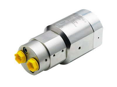
Hydraulic pressure intensifier for high-pressure power packs up to 3,000 bar/43,500 psi
In a typical application, for example, when operating a clamping cylinder, the intensifier is positioned between a directional valve and the cylinder. Connecting the P-port of the intensifier to the pump and the T-port to tank allows the full pump flow to go straight through the integrated check valves in the intensifier, and the cylinder rod will move into position at pump speed. When the cylinder has moved into position and pump pressure has been established inside the cylinder, the intensifier automatically increases the pressure to the required end pressure. As the cylinder now is filled with oil, the pressure increase is done swiftly, typically within a few seconds. In this situation, the intensifier will automatically maintain the pressure. To revert the cylinder rod, the directional valve on the pump side is activated, connecting pump pressure to the intensifier T-port and the P-port is connected to tank. This prompts a pilot signal to an integrated pilot-operated check valve (dump valve or POV), which opens, and creates a direct passage from the cylinder through the intensifier and back to tank.
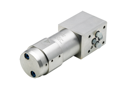
Hydraulic pressure intensifier for Cetop DO3 / NG6 integration
Intensifiers can work with any type of fluid used in standard hydraulic components, including aggressive fluids like Skydrol. They cannot operate with gases.
Specifying hydraulic pressure intensifiers
Four parameters must be considered when specifying a hydraulic pressure intensifier:
- What is the actual requested output pressure that is needed in psi?
- What is the inlet flow in gpm?
- What is the supply pressure?
- How are we going to mount the intensifier solution (flange, brackets, pipe clamp, etc.)? How will it be built into your hydraulic system?
Why should you use an intensifier
Characteristics
- Low operating pressure in the system
- Use existing installed power source
- Use standard tubing, hoses and valves
- Easy to accommodate where needed
- No need for extra tubing or special parts
- Full flow available at pump pressure
- Use existing equipment for the new task
Advantages
- Higher pressure precisely where needed
- Higher pressure by low pressure power source
- Low pressure supply to intensifier
- Intensifiers are compact solutions
- Intensifier fitted directly to cylinder
- Built-in bypass valve and POV
Benefits
- Energy savings for the total system
- No need of expensive horsepower components
- Less cost for the total system and higher safety
- Cost savings by installation
- Cost and space savings by installation
- Fast operation until high pressure is reached
ScanWill Fluid Power ApS / IC-Fluid Power Inc.
icfluid.com
Filed Under: Fluid Power Basics, Fluid Power World Magazine Articles, Slider