
Here are some tips to reduce losses, right-size components and streamline circuits, all of which can lead to sizable cost savings.
Phil McElroy, Product Sales Manager and IFPS-Certified Fluid Power Pneumatic Specialist, Norgren
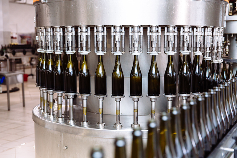
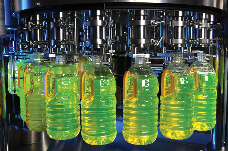
Most industrial facilities depend on compressed air for a range of operations, performed by everything from simple air tools to far-more-complicated pneumatic control systems. In food and beverage processing plants, for example, compressed air systems support functions such as sorting, cutting, shaping, and packaging of products, as well as to blow off particles while cleaning food and equipment.
Compressed air is clean, reliable and accessible but it is often taken for granted when compared to water, gas, and electricity. In addition, it takes approximately eight horsepower of electricity to generate just one horsepower of compressed air. This makes compressed air one of the most expensive energy applications in manufacturing plants.
For a start, compressed air must be available at the proper pressure to achieve production goals. Systems improperly maintained are liable to waste up to one-third of their compressed air because of leaks. Often, drops in air pressure are misinterpreted and mistaken for equipment failure which triggers significant investments in new compressors to increase capacity. Unexpectedly, manufacturers must now absorb the cost of new equipment, rearrange planned schedules and endure downtime while old equipment is being replaced.
System sizing: Understanding Cv
Inefficient use of compressed air is not necessarily a function of machine failure. Instead, problems can occur because of an improperly calculated Cv, a dimensionless number used to express the conductance value of an orifice. Cv is what manufacturers use to size valves and other components when looking at a pneumatic system and is more important to the valve’s performance than the number of cubic feet per minute that passes through.
A valve that is sized correctly will be quiet, have accurate flow control, will not leak, and may even last beyond its expected life span. The larger the Cv, the greater the flow. A valve too small for a given application will not permit sufficient flow-through. When this occurs, the system will be forced to compensate.
Let’s consider an actual situation in which adjustments had to be made to secure maximum efficiency in compressed air operations. The system starts with the compressor, which supplies flow through a receiver tank, supply lines, dryer, filters regulators and valves to a cylinder, with the work application at the rod end. Our goal is to achieve a quicker response in the pneumatic system.
A customer had to move a spool of wire after it had been converted from the main lines from their winders — a material handling task. The application cylinder had a 3.25 in. bore, 10 in. stroke, and we wanted to move that in less than a second. The customer attempted to size the cylinder and a valve needed for the job, but when they put it all together, it was too slow.
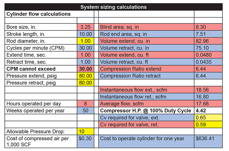
We accounted for the bore, stroke and time to extend, and allowed for a pressure drop of 10 psi in our sizing-software calculations, as shown in the “System sizing calculations” table. We want to get to a higher Cv which would be 0.65 (in yellow) needed for this application. We went with a valve that had a Cv of 1.6. So we had it covered on the valve side. But it still wasn’t fast enough.
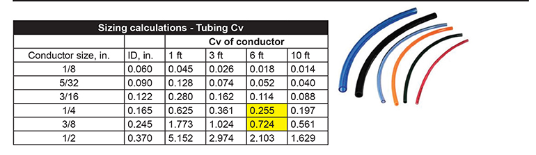
Then we looked at the tubing, which was 1/4 in. tube. From the valve to the actuator the tubing runs approximately six feet. So, with 1/4 in. tubing, the Cv is 0.255. We had choked the system down. So we provided 3/8 in. tubing for a Cv of 0.724. The six-foot span of tubing from the valve should not have been a problem.
But the application was still not fast enough.
We then noticed that mounted on the exhaust ports of the valve were 1/4 in. mufflers with a Cv of 0.1. We removed the mufflers and the Cv restrictions, and then cylinder speeds improved. But the customer still wanted mufflers to keep debris from getting inside the valve and causing issues. So we installed a larger muffler (Cv = 1.4) that provided enough flow for the application and solved the issue.
Leaks and the cost of air
When it comes to generating compressed air, there is no such thing as “free.” If we look at a typical 100-hp compressor, the initial cost for a system may be somewhere in the area between $20,000 and $35,000 (depending on the type of compressor). But the other thing that comes into play, the real cost, is the annual electricity cost, kilowatts per hour for that system. There is also the maintenance cost which annually consists of at least 10% of the actual initial cost of the system.
Consider with the following electricity rates, the annual cost to operate a 100 hp compressor at:
- $0.05/kWh is $26,000.
- $0.10/kWh is $52,000.
- $0.15/kWh is $78,000.
This is the cost to run a motor that obtains the equivalent of the amount of power through the air from a 100-hp compressor, based on three shifts, continuous operation and a full-load motor efficiency of 90%.
What can we do to minimize costs and maximize the efficiency of the compressor? We have to consider the cost of the electricity itself; conversion of electricity to power; maintenance and depreciation; the actual treatment at compression; distribution pipe losses; leaks; treatment at the point of use; and the efficiency of the machine itself. All of these factors can play a role in the cost of air.
And one of the big factors is leaks. As the size of the piping goes up, so does the amount of flow, which means more air passes through, which could mean more wasted money if leaks are present.
There are many sources of leaks — poor connections, damaged or corroded piping, balky seals and pipe joints, drain caps that are open, and machine vibration.
The bottom line is that leaks are expensive. The smaller the orifice size the more difficult it is to notice and sometimes ultrasonic testing may be required for detection. Small leaks can be more prevalent in a system and over a period of time, these leaks can add up. Leaks in larger orifice sizes like 3/8 in. are more audible and easier to detect, but they cost more, given the increased flow.
What are some actions we can take to reduce the amount of leakage? Consider, for example, how many lines are running in your plant. If you have five, and have installed a shutoff ball valve in the main branch of each line but are only operating one line, any leaks in the other lines will not be controlled. So if you can shut off valves to the lines you are not using, there will be cost savings.
Another thing you can do is put a portable flow meter into the system. If the machine is on but not running, and the compressor is off, the flow meter will show if there is airflow while the machine is off, which means there are leaks.
Another factor is a drop in pressure. With constant flow you’ll find the larger or straighter the pipe, the smaller the pressure drops. More-complicated piping with many bends and turns will mean a greater drop in pressure. Thus, try to avoid unnecessary fittings and sharp bends.
Filters protect downstream components like valves and actuators. One area where there can be a high pressure drop is when filters are not properly maintained; if those are clogged, pressure drop over time will increase. Poor filter maintenance is one of the leading causes of pressure drop.
In a properly designed system, the pressure loss is much less than 10% of the compressor’s discharge pressure. For every 2 psi of pressure drop, energy costs increase by 1%. Installing pressure-life indicators will signal when to change those elements.
Dual-pressure circuits
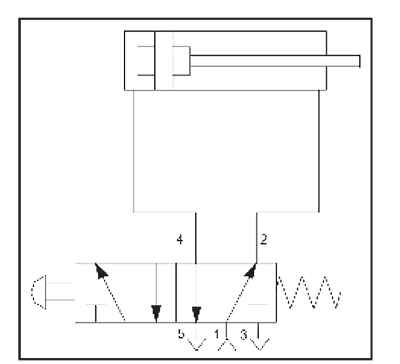
Another factor to consider is the dual pressure circuit. Take a standard circuit with a 5/2 valve and a double-acting cylinder. What you’ll typically find is that most of the work is done on the extension side — 80% to 90% of the time the work is done in one direction. Port 1 is the supply, port 4 is the extension and port 2 is the retraction port. Ports 5 and 3 are exhausts.
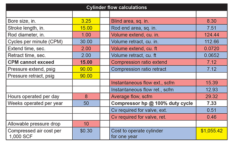
In this example calculation, we have a 3.25-in. bore size, 15-in. stroke, 90.00 psi, one eight-hour shift — resulting in a cost of over $1,055.42 to operate the cylinder for one year.
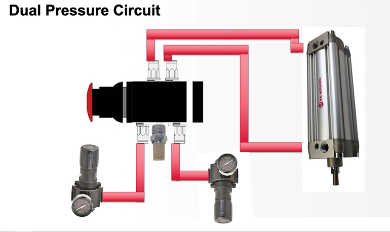
If your application is doing the work in only one direction, consider a dual pressure circuit. Instead of using port 1 for pressure we turn 1 to a shared exhaust; and we put in two different pressures at the exhaust ports. The extend pressure coming through port 3 would be about 117 psi and our return pressure would be 14.7 psi through port 5. So two different pressures, one for main pressure and one to just move the piston and assembly back, especially if there is no load in the opposite direction.
Now, instead of the main air supplying port 1, main air is now going into port 3 and regulated air supplies the return stroke.
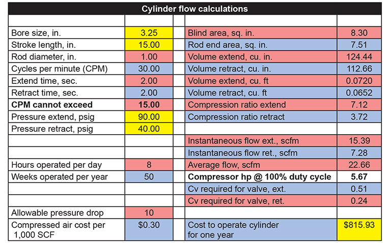
This really makes sense for larger bore cylinders and larger strokes. Look at cost to operate now: with 90 psig both ways it was $1,055. Now, if we lower that return pressure to 40 psig, it’s $815, a saving of $240, with just one cylinder.
Norgren
norgren.com
Filed Under: Pneumatic Tips