
Heat exchangers help remove heat from hydraulic power units, helping to maintain fluid viscosity and reduce wasted energy.
For all its myriad benefits, hydraulics still has a fundamental downside — heat. Adhering to the Laws of Thermodynamics, we must accept that any energy conversion results in increased entropy. In other words, converting mechanical energy from the prime mover into hydraulic energy by the pump is not entirely efficient. In fact, most hydraulic systems waste an excessive amount of energy, unfortunately.
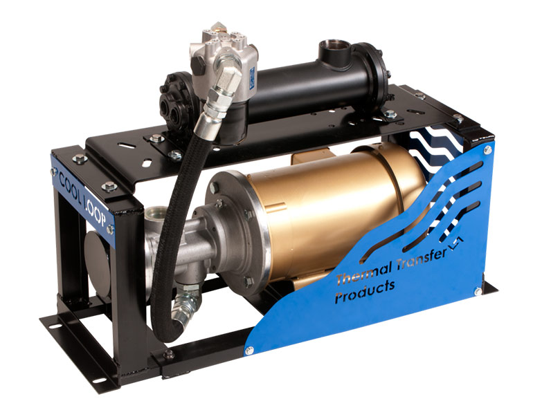
The COLW (Cool Loop, Water Cooled) series is an example of a heat exchanger using shell and tube (finned bundle) design. All images courtesy of API Heat Transfer
Any component bypassing flow without doing useful work squanders every last drop as pure heat. It is common knowledge that pumps create heat. In order of inefficiency rank, the prevailing offenders are gerotor motors/pumps, gear motors/pumps, vane pumps, and then piston motors/pumps. The ranking isn’t concrete, but you get the idea that some offend more than others.
We can’t singularly blame the pump for creating all the heat in our system. The fundamental design plays a large role as well, such as choosing a load sensing, variable flow system over its fixed flow counterpart. Better still, even a servo motor-driven fixed pump controlled in a closed-loop with sophisticated electronics may waste less energy than said load-sensing system.
This article isn’t going to tackle the vast topic of efficient energy use, but rather submit to the heat and discuss how to remove it from your precious hydraulic oil. A heat exchanger transports that entropy away from your power unit, helping maintain ideal viscosity, amongst other benefits. There are two significant methods of heat exchange, each of which employs differing technologies of their own.
Hydraulic fluid may be cooled or heated via either air or liquid transfer. It’s rare to see anything other than an electric heater, so we’ll keep our conversation to coolers. Liquid-to-air and liquid-to-liquid coolers comprise the hydraulic heat exchangers’ two popular choices, which themselves each offer variations.
Liquid-to-liquid coolers
Liquid-to-liquid coolers offer extreme thermal efficiency. The heat transfer rate from one liquid to another is exponentially greater than from a liquid-to-air alone. The thermal efficiency of water or water-based coolant makes the liquid-to-liquid heat exchanger a top choice anywhere water or coolant is freely available in a manufacturing environment.
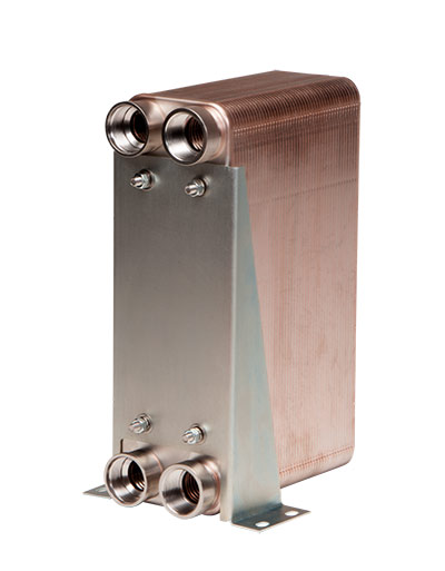
BP industrial hydraulic oil coolers feature a brazed plate design.
The downside to liquid-to-liquid coolers is the clear need for a cooling medium. The municipal water supply provides the easiest access to unlimited water, depending on your geography, since you merely connect the coolant ports to the tap and drain, respectively. However, unless your cashflow provides unlimited resources on par with your tap water, this method is not the most economical.
Manufacturing with access to industrial water supply, such as a river or underground aquafer, can better use open-loop cooling, where wastewater ends up in the sewers or back into the water table. River water offers an advantage over closed-circuit cooling systems; river water is vastly colder unless a chiller is employed. A high delta between the coolant and the hot hydraulic fluid ensures the liquid’s thermal efficiency is exploited.
Closed-circuit (also called closed-loop) cooling systems require exhausting the collected heat away from the coolant. Plants with closed-circuit cooling typically equip a cooling tower outside the facility, either on the roof or at an exterior wall. The tower is a sizeable liquid-to-air heat exchanger, which rejects thermal energy into the atmosphere. Towers are often massive, sometimes larger than a house. A coolant tower cannot cool oil to lower than the outside temperature, making it less effective in the summer or warm climates.
Liquid cooling types
Regardless of your coolant source, the liquid-to-liquid heat exchanger has two major construction types — the shell and tube cooler and brazed plate cooler. Each cooler has its advantages, but often their choice comes down to designer or technician preference.
The shell and tube cooler consists of a series of thermally efficient metal tubes, typically aluminum or copper, running the length of a large tube’s interior. The hydraulic fluid runs through the smaller, interior tubes. With the single pass straight-tube variety, the fluid path is parallel across many tubes brazed or pressed to a plate at either end to separate the media. Ports are located on end faces.
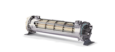
Interior construction of Basco Type 500 shell and tube heat exchangers
The fluid path may snake around through one or many bent tubes, at which point both inlet and outlet ports will be adjacent to each other at one end. This U-tube heat exchanger is simpler to construct since one set of tubes enters and exits on the same endplate.
A semi-hybrid construction is a two-pass cooler, which has elements of the straight-tube and U-tube designs. Fluid enters into one of the baffle-separated coolant ports, flows through the shell to the open-end cap before returning to the ported end. A four-pass design builds on this with a set of baffles guiding fluid through the shell four times to provide the longest dwell time.
The plate cooler is slightly newer to the game but certainly no less effective. They might be the most effective method of transferring damaging heat away from your valuable hydraulic components. They utilize industrial water the same way tube-and-shell coolers do, but they can remove much more heat with any given flow rate.
Plate coolers consist of a set of stamped and sandwiched channel plates. The plates may be manufactured from thin sheets of copper, aluminum or stainless, although many have hybrid construction. A herringbone pattern stamped into the channel plates increases surface area ever so slightly and adds turbulence to the fluid. The turbulence may increase pressure drop slightly but improves cooling enough to offset the downside.
Plate coolers may be manufactured in various ways, although the standouts are the gasketed and brazed configurations. Gasketed plate heat exchangers use thick endplates to sandwich the stamped channel plates together using many tie rods, all sealed with gaskets. This method is easy to manufacture and also easy to modify. To increase flow rate or cooling capacity, add extra sections of channel plates and compress them together with longer tie rods.
The brazed plate cooler is manufactured from similar stamped channel plates but shaped to allow brazing after assembly, permanently fixing the stack together in a small, efficient package. The channel plates alternate in orientation to create separate flow paths for the hot oil and the coolant, leaving just one surface with all four ports. Some consider the brazed plate cooler the new standard in compact, efficient cooling.
Liquid-to-air designs
Most manufacturing plants and all mobile hydraulic machines do not enjoy access to industrial water. A liquid-to-air heat exchanger passes hot hydraulic fluid through its cooling element, where forced airflow evacuates heat away into the atmosphere.
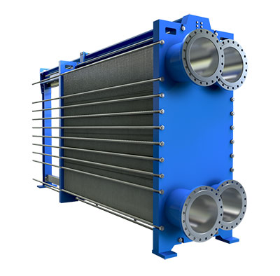
Schmidt Sigma gasketed plate heat exchangers use corrugated plates stacked between a fixed and movable pressure plate. As virtually all of the material is used for heat transfer, they can have large amounts of effective heat transfer surface in a small footprint.
As you would guess, more than one style of liquid-to-air heat exchanger makes its way onto your hydraulic power unit or mobile machine. The venerable tube-and-fin heat exchanger is used everywhere from hydraulic power units to refrigerators and is the most economical heat dispersal method.
The construction quality of tube-and-fin coolers varies vastly, with some a simple fin-covered snaked tube. Like other coolers, the material of choice is copper and aluminum. More efficient tube-and-fin coolers wind a copper tube through lengths of pleated fins, sometimes passing through twice for extra cooling.
Like liquid-to-liquid coolers, liquid-to-air coolers have evolved to improve efficiency. Although tube-and-fin heat exchangers are economical, they simply lack the heat dispersal of their bar and fin sibling. The bar-and-fin cooler uses extruded, hollow bars of aluminum sandwiched between sections of plated aluminum fins. Hot oil flows through the bars to transfer thermal energy to the fins, where high-velocity air carries the heat away.
These well received coolers ensure manufacturers are continually innovating. Each manufacturer offers a unique form of turbulator, which creates thermally efficient turbulence to improve heat transfer. They take the form of nubs, fins, spirals or tabs, and make a significant difference over plain bore fluid channels.
All liquid-to-air heat exchangers are most efficient with the highest possible airflow across their cooling fins. Some mobile machinery may provide that moving air via the engine’s cooling fan, or perhaps even by the vehicle’s velocity. However, the majority of coolers employ some form of fan-operated forced air action.
Electric fans are smart when the extra electrical capacity exists, and manufacturers offer everything from 12 Vdc to 575 Vac electric motors, depending on the applications. Of course, the electric motor’s quality and power vary vastly, ranging from a hundred watts up to 500 W or more.
You haven’t lived, however, until you’ve witnessed the power of a hydraulic motor-driven heat exchanger. Powerful mobile hydraulic machines operating in warm environments need next-level heat dissipation. Imagine a 15-hp cooler moving thousands of cfm on route to a half-million BTU worth of heat removal.
Heat exchangers are critical to the performance and longevity of your hydraulic machinery. Nearly every hydraulic system benefits from extra cooling capacity, and luckily manufacturers offer efficient and economical options for every machine.
Filed Under: Components Oil Coolers, Fluid Power Basics, Fluid Power World Magazine Articles