
Pneumatic grippers are a common and useful way for machines to handle product and other items, but they must be properly selected to match the payload.
Pat Phillips, PE, Product Manager for AutomationDirect, Fluid Power and Mechanical Product Div.
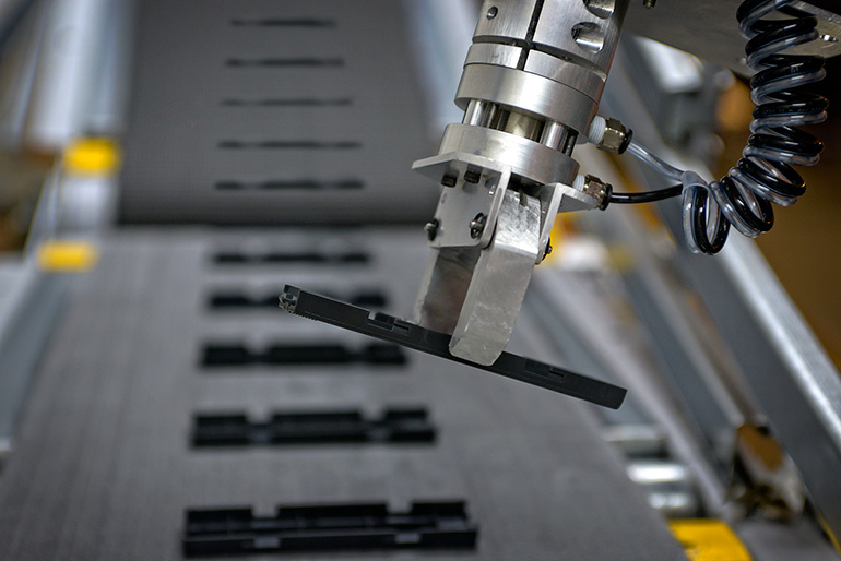
Figure 1. Pneumatic grippers are usually the end effector and must be coordinated with the motion systems on which they are mounted. Image courtesy of AutomationDirect
Prior to the industrial revolution, grippers used in manufacturing were human hands and simple implements. Automation advances and better safety practices improved upon this situation, but required a method to grip and manipulate products, components and tooling. Many of these operations are referred to as pick-and-place systems, and all need a reliable way for the equipment to move a payload.
Therefore, a typical element of many modern material or parts handling equipment are the gripping components. Motion control machinery requires grippers matched to the payload so they can accurately establish a firm and controlled hold without causing damage. The grip must be maintained throughout any motions, and then released to place the payload cleanly.
The first big choice when assessing grippers is deciding among electric, hydraulic and pneumatic technologies. Some applications, especially those for handling fragile product, require extremely fine control and force feedback, making electric a good fit. Other heavy-lifting applications may require the extremely high force available using hydraulics.
However, for many common applications handling relatively robust products, pneumatic gripper technologies are far simpler and more economical. This article focuses on the selection process for pneumatic grippers, although many of the concepts apply to any form of gripper.
Pneumatic benefits
Pneumatic systems in general, and pneumatic grippers specifically, offer many benefits compared to electrical or hydraulic actuation. When pneumatic options are a good fit, they usually represent the lowest initial cost for materials and installation labor, along with low operating costs and ease of maintenance.
Pneumatics are fairly compact and offer a high force density, which is the force they can exert in relation to their size. Compressed air is a relatively safe energy source compared to electricity and works well in wet or corrosive areas. Ongoing costs of generating compressed air and the resulting noise in operation are usually cited as pneumatic downsides, but both issues can be addressed through careful design and compressed air is widely used in many types of facilities.
Once the choice of going pneumatic is settled, the design process moves into selecting the proper type of gripper action.
Gripper types
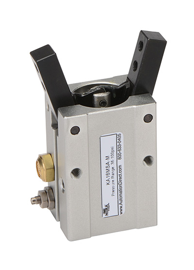
Figure 2. Available in many dimensional sizes, this family of AutomationDirect Nitra angular grippers are optimized for handling flat or sheet objects. Image courtesy of AutomationDirect
A gripper is sometimes called a clamp or may more generally be termed as the end effector of a motion system. There are two basic gripper types, angular and parallel, based on the geometry and the way the jaws work. Certainly, there are many other variations and specialty styles of grippers, but these two are the most common.
Gripping can be accomplished upon closing on the outside of a payload, or upon opening on the inside of a payload. For pneumatic grippers, there is generally a small linear pneumatic cylinder within the body of the gripper. This cylinder is arranged with a mechanism to translate the linear cylinder action into either a pinching angular action or a sliding linear action. The pneumatics may be single-acting, using air to operate the gripper one direction and a spring to close it the other, or they may be double-acting, where air pressure is required to both open and close the gripper.
Angular grippers are more economical than parallel because they have a simpler pivot-based mechanism (Figure 2). However, it is evident that they are best suited for gripping flatter objects and may not grip well on parts with curved or parallel sides.
Parallel grippers are a better choice for relatively larger payloads, especially those with parallel sides available (Figure 3). They are slightly more expensive and complicated than angular grippers due to the mechanism needed to translate the cylinder linear motion so that the two fingers slide directly to and from each other.
Solving the grip motion is just part of the physical solution, since the actual way the gripper contacts the product must also be considered.
Making contact
Both angular and parallel grippers end up moving appendages called fingers, which in turn contact the payload. Many configurations are available for starting and ending grip angle, gripper stroke travel, motion repeatability and finger sizes.
Users may simply take advantage of the plain fingers of a gripper to hold the payload, or they may make their own finger attachments out of materials more compatible with the parts being handled. Customized fingers can be curved or shaped to encompass or more positively hold a payload. The material choice of the payload side of a gripper finger can optimize grip friction using resiliency and may prevent the gripper from marring the part.
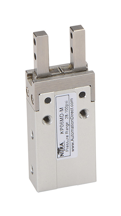
Figure 3. Parallel grippers, such as this AutomationDirect Nitra version, come in many size configurations and offer good holding power for flat-sided payloads. Image courtesy of AutomationDirect
Making the right choices for grip stroke, finger shaping and finger materials will also help the assembly to accept dimensional variations in payloads, misalignments as the gripper is operated or slight differences in gripper motion repeatability. Some of these considerations are also related to the larger mechanism transporting the gripper.
Another specification concerns the air pressure to be used to achieve a desired gripping force. Users must calculate or determine through testing what a sufficient but not excessive gripping force is. The desired operating pressure in conjunction with the gripper cylinder size will result in a certain gripping force, so all three of these values — air pressure, cylinder size and gripping force — must be considered in conjunction and coordinated.
Integrating grippers into a system
Grippers are usually the end effector of a much larger equipment motion system, such as an XYZ pick-and-place system or even a fully articulated robot arm (Figure 1). This means there is a substantial amount of integration and coordination of a gripper required with the upstream electric or pneumatic actuators, stepper or servo motors, drives, other motion controllers and even programmable logic controllers (PLCs).
Grippers may be a relatively inexpensive part of such a system, but if they can’t perform their required function then nothing gets done. Some typical control elements necessary to command pneumatic grippers in this type of a system are:
- Solenoids so the PLC can operate the compressed air to open/close the gripper
- Fittings, tubing and hose to route compressed air to the gripper in a flexible manner
- Exhaust mufflers to silence the vented side of a gripper cylinder
- Flow restrictors to slow down the action of a gripper and prevent hammering
Another mechanical consideration regards the cycle rate, which is how many times per minute the gripper is rated to operate. Most grippers actuate quite quickly, but the manufacturer typically publishes the allowable upper limit for how often they can be cycled. Users must evaluate the application to ensure the cycle rate is adequate.
With the pneumatic side sorted out, attention turns to the electrical and control side of the operation.
Feedback options
For some applications, it may be satisfactory to simply command the gripper and configure the controls to assume it has moved. However, in most cases best practice is to positively sense the gripper’s open or closed position for more positive operation, and to generate an alarm if the gripper fails to move to the commanded position.
Because position feedback is such a common requirement, many pneumatic grippers are designed with magnetic pistons within the cylinder and slots on the side to accept standard position switches. Magnetic pistons serve as a target detectible by position switches. Users can adjust the switches to indicate any position of the gripper based on the piston position, so the desired gripper position can be matched to indicate if the gripper is open, closed or properly holding a part.
It may also be prudent to monitor pneumatic pressure, which can be accomplished in one of two ways. The simplest way is to use a pressure switch, usually installed on the air supply line but possibly installed after the gripper solenoid, to ensure that a sufficient operating pressure threshold has been met or exceeded. For many applications, this is good enough to verify the operation.
For more critical or delicate gripper operations where precise supply pressure is crucial to ensure the exact desired gripper force, users may install a pressure transmitter so the PLC controls can verify correct pressure and alarm otherwise. The pressure would usually be manually set using an upstream pressure regulator, and the controls would therefore monitor to ensure the pressure hasn’t deviated from the desired value.
Getting a grip
Grippers are a fundamental element for many types of equipment automation, and they are literally the final interface where the equipment meets the product. Pneumatic grippers are a good choice technically and economically for many automated equipment applications, with the two main gripper types being angular and parallel.
Designers must work through physical force and dimension requirements to select the right gripper. Some suppliers provide online selection guides to assist users in choosing the right gripper for an application. These guides can direct users in considering options such as the gripper action, size and limit switches to closely integrate the gripper with the automation and the rest of the equipment. Since pneumatic grippers are a popular technology, suppliers can also be a good support resource to help designers choose the best option for their application from the many available configurations.
AutomationDirect
www.automationdirect.com
Filed Under: Pneumatic Tips