
Hydraulic pumps are primarily designed to convert incoming prime mover energy into hydraulic energy, manifested as pressure and flow. The term hydrostatic refers to a state of pressure equilibrium, especially in a confined space. All traditional hydraulic applications are hydrostatic, and in most cases, if you shut down the pump, physical loads should hold fast using the already pressurized hydraulic oil.
It would be easy if everyone used hydraulic pumps for hydraulic applications, but not everyone seems to like things easy. For example, I can think of a dozen ways to lubricate a CNC machine or large bearing, and even if the lubrication medium was hydraulic fluid, I could think of better pump designs for this application. Still, some spindles require hydrostatic bearing support for very high-speed machining, so sometimes high-pressure hydraulic fluid is the only solution.
You’d be surprised to know how often hydraulic pumps are used for water-based coolant for CNC machines. Although hydrostatic bearings absolutely require high pressure to support the assembly, using them for coolant is a surprising take on the pressure compensated pump. Dynamic pumps use impellers to essentially throw the fluid to create inertial pressure, much like the impeller on a boat. You can cap the outlet port of a dynamic pump just the same as you can a pressure compensated piston pump.
I suppose engineers started using pressure compensated pumps for cooling because of their ability to maintain a set pressure even when downstream flow paths wear, such as with orifices inside of tooling. Through-tool coolant will slowly erode the internal diameter of its flow path, which increases the effective orifice size, thereby reducing pressure drop. So long as the pump is oversized for the application, it will maintain the pressure compensation set point despite downstream increases in orifice size (to a point).
However, there are right and wrong ways to use hydraulic pumps for lubrication and coolant. For example, variable displacement axial piston pumps are overbuilt for these applications, mainly because they handle thousands more psi than any lubrication or coolant application needs. At the same time, these pumps actually require a minimum operating pressure.
Although minimum compensator pressure depends on the make and construction of the pump, expect minimum pressure of at least 200-300 psi. Unlike gear pumps, for example, the pressure compensated pump has many parts engineered to operate effectively only when pressure exists. For example, the compensator, control piston, and (sometimes) the bias piston run from pilot pressure, but pressure is required to keep the entire pump under tension.
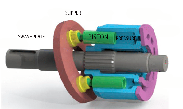
Refer to the image, which shows the major components of the pump’s rotating group. As the blue cylinder block rotates, the swashplate angle forces the pistons to reciprocate, which in turn pumps fluid. As the piston passes “top dead center” and begins to retract into the block to create pressure, the entire assembly maintains tension until the piston again extends to suck in the fluid.
Without pressure, there exists no tension in the rotating group. With no tension, the entire assembly is a floppy collection of metal parts banging and slapping as they reciprocate and rotate at maximum displacement because no hydraulic pressure exists to bring the pump on standby. Hydraulic oil feeds typically down through the hollow pistons where a pinhole in the socket feeds pilot pressure to keep the slippers lubricated against the swashplate, but with no standby pressure, no lubrication occurs.
If you are using, or are considering using, a hydraulic pump for your lubrication or coolant application, you must guarantee your pump never drops below its minimum pressure rating. This may occur from orifice wear, but I’ve also seen hydraulic circuits designed to “unload” the pump when coolant isn’t required. You’re better off installing a poppet valve to block outlet flow than to unload the pump because only running with no oil will damage a pump faster.
Filed Under: Components Oil Coolers, Engineering Basics, Mobile Hydraulic Tips, Pumps & Motors