
I’ve explained other compound symbols in previous Symbology lessons, although not from the specific perspective of intentionally using two or more combined symbols to make one complete, functional component. The detailed version of the pressure compensated pump symbol combines tiny cylinders with 3-way, 2-position regulators and a smattering of other small symbols to make one giant symbol — that symbol closer to a full schematic. This article focuses on the compound components using two or more symbols to construct a more complicated form of the same part.
In machines using a hydraulic motor, you must take care to prevent the inertia of the load from negatively affecting both the machine and the hydraulic system itself. A rotating mass has momentum that persists despite your desire to slow or stop it via the directional valve control. A high-speed winch, for example, would like nothing more than to carry on rotating after the directional valve is closed, or even worse if you reverse the valve.
When a directional valve closes while an inertial load still moves, the nearly incompressible hydraulic fluid spikes in pressure while the machine jolts to a sudden stop. You risk both mechanical breakage and blown seals as the impeded energy finds the path of least resistance.
Want more symbology content? Download our 45-page Symbology Building Blocks e-book now.
A crossover relief valve (also known as a cross port relief valve) installed parallel with the motor work lines protects your machine from damage caused by rapid stopping action. In Figure 1, I’ve drawn such a valve upstream of the hydraulic motor. Although you can create the desired effect using two separately plumbed individual relief valves, the single-block design of the crossover relief saves the cost of plumbing while reducing leak points.
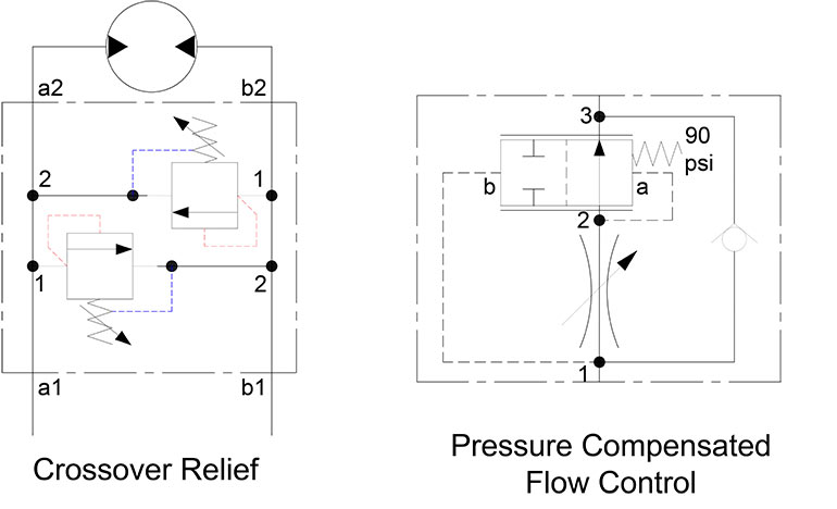
Compound Symbols Figure 1
Ports a1 and b1 connect upstream to the directional valve. It’s essential to know the directional valve would have both work ports blocked in the neutral position. You don’t need a cross port relief when A & B are open to tank. The “float center” spool configuration (often called a motor spool) works because it combines the work ports in the center condition, allowing the motor to spin down under its inertia (or perhaps using a brake valve).
Ports a2 and b2 connect downstream of the motor, which, as you’ll remember from the dual inward-facing arrows, tells us the motor is bi-rotational. As the motor rotates, fluid happily travels through a1 to a2 under pressure and then back through b2 and b1 at low pressure, since the hydraulic energy gets consumed at the motor.
Imagine now that the directional valve slams shut, with fluid blocked from exiting port b1 while fluid can no longer enter through a1. Without the crossover relief valve in place, the cavity between a1 and a2 would cavitate under negative pressure. The passageway between b2 and b1 would spike pressure dramatically because both fluid and motor inertia have nowhere to dissipate.
With the crossover relief protecting the circuit, this time when the valve closes, any excess pressure in the line b2-b1 acts upon the port 1 of the relief valve. With the a1-a2 side still cavitating slightly, fluid from the high-pressure side is welcomed to fill the void. The crossover relief valve brakes the motor, turning the inertia of its mass into heat across the relief valve. The motor slows rapidly but in a damped motion that can be tuned by the pressure settings of the cross port relief valves.
Because the system is symmetrical, it’s clear that when the motor direction reverses, the same damping effect slows the motor in a controlled fashion without shocking or damaging the machine or the system. You’ll note I’ve shown the blue drain lines, starting from the spring chamber and terminating at the low-pressure side of the relief. The drain ensures the spring chamber drains of pressure to prevent that pressure from adding to the spring value or even locking up the relief valve altogether. A drain is typical for any component exposed to pressure at both work ports.
I covered the second component in Figure 1 in a previous Symbology article, but I thought it was important enough to mention again as a compound symbol. The pressure compensated flow control often gets drawn in its simplified form, but the one depicted does a much better job of showing how the valve balances for differences between upstream and downstream pressure that reduces pressure drop, and therefore, flow.
The 2/2 component downstream of the needle valve is the compensator. In this case, the 90 psi spring offsets the valve, allowing relatively free flow from port 2 to port 3. The functional key to this symbol happens with ports b and a of the compensator. As flow is directed from port 1 to port 2 at a reduced rate by the needle valve, back pressure rises at port 1 inversely proportional to the flow setting. The pilot line feeds port b of the compensator, where it pushes the compensator’s spool against the pressure of the spring.
Port a connects directly downstream of the needle valve at 2, where it avoids the backpressure at 1. In fact, the whole point of the compensator is to compare ports 1 and 2 and maintain exactly 90 psi of pressure drop through the needle valve. With a standard needle valve, any load-induced pressure increased at port 2 causes a reduction in pressure drop across the needle valve. Flow potential is equally factored between pressure drop and the size of the orifice, so as downstream pressure increases, the flow rate decreases relative pressure differential.
As load pressure increases, that increased pressure feeds to port a to open the compensator further, increasing the effective orifice size flowing from 1 to 3. Regardless of downstream load pressure, the compensator opens up further as required to maintain the 90 psi pressure drop it measures between port 1 and port 2.
I’ve drawn a pilot-operated relief valve in Figure 2. As you’ve probably figured out by now, when it comes to high flow hydraulic components, it isn’t effortless to directly control high flow components with springs or solenoids. Pilot control takes advantage of the power density of hydraulics to turn some components into mini actuators, as it were.
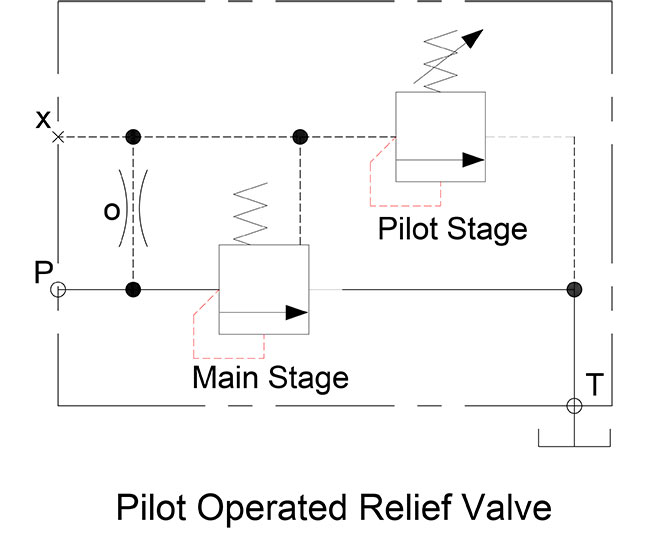
Compound Symbols Figure 2
A high flow relief valve requiring pilot operation flows at least 30 gpm but can handle thousands of gpm in some applications. I’ve shown two relief valves plumbed in parallel with common pressure and tank connections. The P port of the valve block feeds the Main Stage valve but not before a connection node branches off upward through the orifice at o. You’re notice all lines on either side of the Main Stage valve are solid, yet most others are the dashed pilot lines, which accurately describes their size.
The fixed orifice limits flow so as not to oversaturate the Pilot Stage relief, which likely flows less than a gallon per minute. The pilot line connects through a node to the pilot pressure line denoted as x, which is standard practice for all hydraulic pilot pressure sources (y is the denotation for pilot drain, by the way). Continuing downstream to the next node, you can see the pilot line feeds down to the spring chamber of the Main Stage relief valve. You may have also noticed there is no variable symbol atop the Main Stage spring.
The pressure control occurs through the Pilot Stage, which is a tiny relief valve selected to control pressure in the x passage of the combination valve. The pilot valve remains closed until the pressure at port P rises above the pilot valve pressure setting, where the pilot valve starts to open to bleed off x passage flow. The pilot valve’s path to tank allows the Main Stage valve to overcome its own pressure setting (which is a combination of its fixed spring pressure and the pilot pressure of the pilot valve).
The two valves work in tandem to allow high flow pressure relief with accurate control. The X port shows as being blocked. However, if the valve operates in a hydraulic system with a dedicated pilot supply, that source is plumbed to the x port. In this case, I show the orifice plugged to separate the primary hydraulic supply from the pilot network.
The x port also allows a secondary pilot control option, which may use a solenoid valve to dump pilot pressure to tank, essentially turning the main stage valve into an unloading valve. Or the pilot supply could come from a proportional pressure reducing valve that can electronically change the pressure in the pilot supply, so long as its lower than the setting of the Pilot Stage valve.
Filed Under: Fluid Power Basics