
Any book or lesson in fluid power worth its weight in gold will discuss the importance of electrical and electronic control of hydraulics. In fact, over the past few decades, most advancement in hydraulics has been in how it’s controlled rather than improvements in the foundational components such as valves, pumps and actuators.
Understanding electrical symbology becomes more important as machinery becomes more sophisticated, and you may come across schematics that are hybridized with electronics or even electric actuators like linear or servomotors. This chapter of hydraulic symbology covers most of what needs to be known to read and create the average hydraulic schematic, since actual electrical symbols are somewhat different.
Starting with Figure 1, there are three ways to draw an electric operator for solenoid valves, which most people recognize. The first operator is the symbol for a solenoid coil that magnetically pushes on the armature pin, which makes sense as the diagonal line leans towards the valve body. When you flip the diagonal line to lean outward from the valve body, the coil now shifts the valve by pulling on the armature pin, although it is rare to see the symbol drawn this way. Most often a valve will be drawn as though the inward-facing coil symbols are the standard, and it’s even my personal preference.

Figure 1. Electrical operators
Want more symbology content? Download our 45-page Symbology Building Blocks e-book now.
When the valve is manufactured with dual, opposed coils, such as with a 3-position cartridge valve, you draw the symbol with both of the diagonal directions as shown. Because the end of the valve opposite the coils is buried within a manifold or ported body, the only place to mount two coils is on the top. Inside the core tube, the armature pin is attached to the spool and can be pushed or pulled off-center by either coil.
Figure 2 shows three options for drawing proportional valve symbols. A generic proportional valve symbol is shown on the left and is quite simply a diagonal variable arrow slashed across the coil symbol. This denotes that the current applied to the coil can be varied (typically via pulse width modulation), and the two parallel lines above and below the valve symbol tells us the valve spool is constructed in such a way to have infinitely variable positions between fully closed and fully flowing. However, like many symbols, it tells us nothing of the construction technique or method of manufacture.
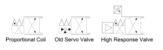
Figure 2. Proportional coils
The symbol previously used to represent servovalves is still commonly found in old schematics, literature and documentation. It’s an odd symbol, unique to servovalves, but makes perfect sense when broken down. It varies from the newer proportional valve symbol only by the operator (the spring and parallel lines showing infinite positionability remain). The blank circle is surrounded by three triangles, each of which pointing into or away from the circle.
The left side triangle represents the input to the valve, which is the desired signal sent from the controller. The right side line and arrow depict the actual output being applied to the valve. The bottom triangle facing up into the circle is the closed-loop feedback being added to the control signal, which is the amount of correction equal to the difference between the input and output. An actual servovalve has an inherent feedback loop using nozzles and a spool position-sensing flapper that creates backpressures. It’s a complex task, but it’s only important you know what the symbol means at this point.
The high response valve on the right in Figure 2 shows another method of closed-loop valve control. This symbol is a mix of the two earlier examples, but instead of inherent feedback of the servovalve, it uses on-board electronics. The big dashed-line triangle is the electronic symbol for an amplifier, although, in the electrical symbology realm, the triangle is an unbroken, solid line. When the symbol is borrowed for fluid power use, the line is dashed as to not be confused with a pneumatic pilot source.
The amplifier is on-board the valve and is supplied with a corrected signal with help from closed-loop position feedback. The box perched atop the valve symbol and stemming from an extension of the infinite position line is the symbol for a linear transducer. The diagonal line is used for most fluid power transducers and is used to show a separation from the mechanical property and the electronics. The G comes from the German word geradlinig, meaning rectilinear, although sometimes the letter S is used. The U is just a generic curve that tells us there is an analog signal involved capable of infinite positioning up and down a curve.
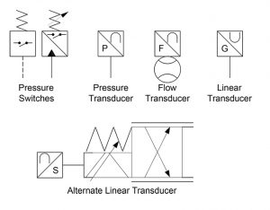
Figure 3. Switches and transducers
Figure 3 shows various other transducer symbols but actually starts with a pressure switch drawn as two variants. The first shows the dashed pilot line you learned about in the very first Hydraulic Symbology 101 article. That pilot signal will push to close a switch when the pilot force is enough to overcome the spring valve opposing the pilot energy. You’ll notice there is no variable arrow in this symbol, telling us the pressure setting is fixed from the factory.
A side note for electric switches; a normally open electrical switch means electrons are not flowing as the switch contacts are not touching. In fluid power, a normally open valve flows fluid in its neutral position. A closed electrical switch means the electrons are flowing and the component is doing its job. In fluid power, a closed valve is not flowing any fluid, so ensure you are aware of the differences and don’t confuse them.
The next pressure switch example is the current ISO pressure switch standard and makes a few changes from the older one on the left. It first shows a triangular pressure signal coming in the bottom, where the fluid is separated by some sort of membrane depicted by the diagonal line. That membrane would then act upon the “normally open” switch above it. Finally, I’m certain you knew this was an adjustable pressure switch by the spring and variable symbols added above.
Going down the line, I’ve added three more transducers, all remarkably similar but the letters used and the circular object below the flow transducer. The P in the pressure transducers obviously stands for “pressure,” and it shares the “analog” curve symbol in the opposing corner. This symbol isn’t a “U” shape as shown on the high response valve symbol but is instead upside down. Although I haven’t seen consistent use of this symbol in any one direction, it is most often drawn as shown in this pressure transducer symbol.
The flow transducer is mounted atop the symbol for a flow meter. All mechanical measurement symbols employ a circle, such as with the pressure gauge or thermometer, and you must imagine that fluid passes horizontally through the convex shapes where its rate of flow is measured. In reality, this can take place via myriad methods, once again making it clear symbology is a representation of what is occurring, but not how it is occurring.
The linear transducer was already described in Figure 2, but I decided to add an alternate configuration attached to a proportional valve. I also used the alternate S designation, which is a mathematical symbol sometimes used for displacement or distance. Overall, the symbol is quite similar to the high response valve, but the proportional coils are the dual-opposed type, each pushing on the same armature pin, albeit in different directions.
Although not a comprehensive list, these electrical and electronic symbols explained will arm you with the essentials of electronic control of hydraulics, and with the depicted patterns already shown to be obvious, any new symbols will be easy for you to decipher.
Filed Under: Fluid Power Basics, Sensors, Sensors & Gauges, Valves & Manifolds