Fluid Power World

  • Home
  • Technologies
    • Hydraulics
      • Cylinders & Actuators
      • Filtration/Contamination Control
      • Fittings, Couplings & Adapters
      • Fluids
      • Fluid Conditioning
      • Hose & Tubing
      • Pumps & Motors
      • Related Technologies
      • Sealing
      • Sensors & Gauges
      • Valves & Manifolds
    • Pneumatics
      • Air Preparation & Regulation
      • Compressed Air Technologies
      • Cylinders & Actuators
      • End Effectors & Grippers
      • Fittings, Couplings & Adapters
      • Hose & Tubing
      • Sensors
      • Vacuum
      • Valves & Manifolds
  • Engineering Basics
  • Trending
  • Resources
    • Digital Issues
    • Pneumatics Tech Toolbox
    • Podcasts
    • Subscribe to Fluid Power World Print Magazine
    • Videos
    • Webinars / Digital Events
    • White Papers
  • Women in Engineering
    • Women in Fluid Power
    • Women in Engineering
  • Design Guide Library
  • Classrooms
    • Pneumatics Classroom
  • SUBSCRIBE

How do directional seated valves operate?

By Mary Gannon | December 1, 2021

Share

By Josh Cosford, Contributing Editor

In the most traditional sense, a directional control valve simply dictates the direction of hydraulic flow in some regard. The inline check valve is generally regarded as the most basic version of a directional valve, and simply allows flow in one direction while blocking flow in the opposing direction. Their advantage lies in their simple, reliable and leak-free design, and when used as solenoid actuated directional valves, these poppet valves benefits make them superior to spool valves in many ways.

Figure 1. Directional seated valves

The difficulty using poppet valves to control actuators arises when the two-way, two-position nature is asked to move fluid in four ways instead. Asking a 2/2 valve to mimic a 4/3 valve actually takes four of said 2/2 valves. However, most manufacturers offer 3/2 poppet valves that allow one flow path open while the other remains closed. When combined, two 3/2 valves can mimic the operation of a single 4/3 valve, albeit with more limited center conditions (the paths of the A, B, P and T ports when unshifted).

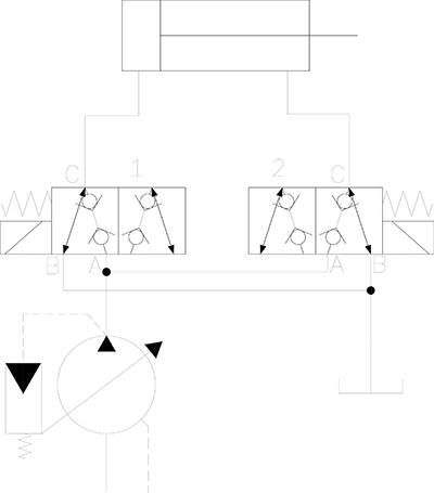
In Figure 1, I show how such a control circuit looks when using two 3/2 valves in place of a 4/3 directional valve. Each 3/2 poppet valve is spring offset and solenoid operated. In their neutral positions, each of the valve’s A-port connects to the outlet of the variable displacement pump, where it remains on standby since there is no flow path through the valve.

With the flow path C to B open on valves, the workports from the cylinder remain open to tank, leaving the cylinder in a float position. If compared to a single 4/3 directional valve, these two valves create a float-spool center, which is also called a motor spool. Should you wish to cycle the cylinder, simple energize the coil of the valve connected to the port you wish to extend from.

Activating the Valve 1 solenoid shifts the left-side valve, sending pump flow to the cap side port, extending the cylinder. Valve 2 may remain unshifted since it allows rod port flow directly to tank. Should you wish to retract the cylinder, close Valve 1 and provide power to Valve 2, retracting the cylinder. This configuration offers advantages beyond a standard monoblock or solenoid operated valve regeneration. Should you wish to extend the cylinder rapidly, energizing both solenoids at once opens both cylinder work ports simultaneously, connecting rod and cap ports to extend the cylinder rapidly.

Figure-2---Poppet-Cutaway
Figure 2. Poppet cutaway

The above creative use of circuitry is possible without a seated valve, of course. Simple 3/2 spool valves offer the same flexibility. However, the seated valve provides something no spool valve can – high pressure operation with little to no leakage flow.

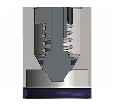
As you can see from Figure 2, when flow attempts to travel from port 2 (top) to port 1 (bottom), the more pressure exerted in an attempt to pass will result in more force of the poppet against its seat. Many directional seated valves are rated to 10,000 psi (700 bar), making them one of the only solenoid valve options for high pressure hydraulics.

Because of the contact area of the poppet against the seat (especially in valves with polymer seals), leakage is extremely limited. Applications requiring low leakage, such as clamping functions for CNC mills, allow clamps to maintain their grasp on parts for extended periods even when not pressurized by the pump. In fact, many of these machine tool applications use a detented valve that leaves the valve shifted without any coil power for as long as the CNC program requires.


Filed Under: Engineering Basics, Mobile Hydraulic Tips, Valves & Manifolds


About The Author

Mary Gannon

Mary Gannon is editor of Fluid Power World. She has been a technical writer and editor for more than 13 years, having covered fluid power, motion control and interconnect technologies.

Current Digital Issue

  Easier access to more of our content Every other month, readers of Fluid Power World have access to our beautiful print and digital editions, where we share a selection of the best fundamentals content, technology news, case studies, and technical articles that cover the gamut of hydraulics and pneumatics system design. But we only…

Subscribe!

Fluid Power World is written by engineers for engineers engaged in designing machines and or equipment in Off-Highway, Oil & Gas, Mining, Packaging, Industrial Applications, Agriculture, Construction, Forestry, Medical and Material Handling. Fluid Power World covers pneumatics, mobile hydraulics and industrial hydraulics.

Fluid Power Design Guides

fluid
“fpw
EXPAND YOUR KNOWLEDGE AND STAY CONNECTED
Get the latest info on technologies, tools and strategies for Fluid Power Professionals.

RSS Featured White Papers

  • Moving fluid power forward
  • High-force linear motion: How to convert from hydraulic cylinders to electric actuators and why.
  • A technical comparison: Performance of pneumatic cylinders and electric rod actuators
Fluid Power World
  • Hose Assembly Tips
  • Mobile Hydraulic Tips
  • Pneumatic Tips
  • Sealing & Contamination Control Tips
  • About us
  • Contact Us

Copyright © 2024 WTWH Media LLC. All Rights Reserved. The material on this site may not be reproduced, distributed, transmitted, cached or otherwise used, except with the prior written permission of WTWH Media
Privacy Policy | Advertising | About Us

Search Fluid Power World

  • Home
  • Technologies
    • Hydraulics
      • Cylinders & Actuators
      • Filtration/Contamination Control
      • Fittings, Couplings & Adapters
      • Fluids
      • Fluid Conditioning
      • Hose & Tubing
      • Pumps & Motors
      • Related Technologies
      • Sealing
      • Sensors & Gauges
      • Valves & Manifolds
    • Pneumatics
      • Air Preparation & Regulation
      • Compressed Air Technologies
      • Cylinders & Actuators
      • End Effectors & Grippers
      • Fittings, Couplings & Adapters
      • Hose & Tubing
      • Sensors
      • Vacuum
      • Valves & Manifolds
  • Engineering Basics
  • Trending
  • Resources
    • Digital Issues
    • Pneumatics Tech Toolbox
    • Podcasts
    • Subscribe to Fluid Power World Print Magazine
    • Videos
    • Webinars / Digital Events
    • White Papers
  • Women in Engineering
    • Women in Fluid Power
    • Women in Engineering
  • Design Guide Library
  • Classrooms
    • Pneumatics Classroom
  • SUBSCRIBE