Fluid Power World

  • Home
  • Technologies
    • Hydraulics
      • Cylinders & Actuators
      • Filtration/Contamination Control
      • Fittings, Couplings & Adapters
      • Fluids
      • Fluid Conditioning
      • Hose & Tubing
      • Pumps & Motors
      • Related Technologies
      • Sealing
      • Sensors & Gauges
      • Valves & Manifolds
    • Pneumatics
      • Air Preparation & Regulation
      • Compressed Air Technologies
      • Cylinders & Actuators
      • End Effectors & Grippers
      • Fittings, Couplings & Adapters
      • Hose & Tubing
      • Sensors
      • Vacuum
      • Valves & Manifolds
  • Engineering Basics
  • Trending
  • Resources
    • Digital Issues
    • Pneumatics Tech Toolbox
    • Podcasts
    • Subscribe to Fluid Power World Print Magazine
    • Videos
    • Webinars / Digital Events
    • White Papers
  • Women in Engineering
    • Women in Fluid Power
    • Women in Engineering
  • Design Guide Library
  • Classrooms
    • Pneumatics Classroom
  • SUBSCRIBE

What are accumulator safety blocks?

By Mary Gannon | July 20, 2022

Share

By Josh Cosford, Contributing Editor

Hydropneumatic accumulators combine the power density of hydraulics with the compressibility (and expandability) of air. The accumulator itself uses either bladders, diaphragms or pistons to separate the gas side from the hydraulic side. The air side is pre-charged with nitrogen gas to a pressure appropriate for the application. Nitrogen is used for its non-reactive nature and may be charged up to 2,000 psiI or more. The gas volume of an accumulator may range from fractions of a liter up to 15 gal or more, allowing about a third of such volume to be used as hydraulic flow, give or take.

Parker accumulator safety blocks

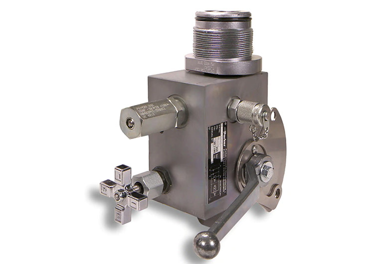
Accumulator safety blocks. Image courtesy of Parker Hannifin

During operation, pressurized fluid is directed into the accumulator, which compresses the nitrogen until the gas compresses to the point that its pressure equalizes with system pressure. Once downstream pressure drops below system pressure, such as when a function is activated, the compressed gas forces hydraulic fluid from the accumulator’s fluid port.

The vigor in which the accumulator sends fluid depends on the pressure differential at the downstream load or restriction.
Because accumulators store potential energy much like an electrical capacitor, the possibility of accidental discharge must be respected. In fact, a large accumulator storing hydraulic fluid under high pressure may release the entirety of its energy within seconds, equating to perhaps hundreds of horsepower in some cases. The possible danger is very real, and all precautions must be taken to safely and reliably contain the accumulator’s stored energy.

Should one or more accumulators exist in your hydraulic circuit, special valves must be installed to control and direct accumulator energy. Then, when the machine shuts down, either intentionally or via an emergency stop, operators and service personnel need not guess if the accumulators contain potentially dangerous pressurized fluid. A normally open solenoid valve teed off from the accumulator pressure port should open to direct fluid to the reservoir as a default safety feature. Such a valve should also include an orifice to prevent saturation of the tank line and potentially damaging return line filters or other equipment downstream.

Although designing a safety circuit for an accumulator would be relatively straightforward, time and cost can be saved by purchasing a stand-alone accumulator safety block. These safety blocks contain all the necessary valves and components to keep the accumulator safe when not in operation. The blocks generally have three ports, one pressure out, one for the reservoir and a third close-coupled to the accumulator itself.

Internal to the valve block is a series of valves to passively and actively control the energy state of the accumulator. A locking ball valve provides the first line of defense – a technician who performs maintenance on the machine may lock the accumulator into the tank drain position to guarantee the accumulator cannot be charged should the machine inadvertently be turned on. Once maintenance or service completes, the technician removes the lock and closes the valve, so the accumulator again holds pressure.

A second ball valve installed into the manifold closes to block incoming pump fluid, providing important redundant safety for the machine and technicians alike. A relief valve installed parallel to the ball valves limits pressure inside the accumulator. It must be set higher than the system relief valve to prevent pump pressure from draining directly to the tank. The optional solenoid valve, as discussed earlier, provides yet another safeguard to ensure no energy remains stored when you shut the machine down. A pressure gauge in the accumulator port offers a visual guarantee that the accumulator remains drained.


Filed Under: Accumulators, Components Oil Coolers, Engineering Basics


About The Author

Mary Gannon

Mary Gannon is editor of Fluid Power World. She has been a technical writer and editor for more than 13 years, having covered fluid power, motion control and interconnect technologies.

Current Digital Issue

  Easier access to more of our content Every other month, readers of Fluid Power World have access to our beautiful print and digital editions, where we share a selection of the best fundamentals content, technology news, case studies, and technical articles that cover the gamut of hydraulics and pneumatics system design. But we only…

Subscribe!

Fluid Power World is written by engineers for engineers engaged in designing machines and or equipment in Off-Highway, Oil & Gas, Mining, Packaging, Industrial Applications, Agriculture, Construction, Forestry, Medical and Material Handling. Fluid Power World covers pneumatics, mobile hydraulics and industrial hydraulics.

Fluid Power Design Guides

fluid
“fpw
EXPAND YOUR KNOWLEDGE AND STAY CONNECTED
Get the latest info on technologies, tools and strategies for Fluid Power Professionals.

RSS Featured White Papers

  • Moving fluid power forward
  • High-force linear motion: How to convert from hydraulic cylinders to electric actuators and why.
  • A technical comparison: Performance of pneumatic cylinders and electric rod actuators
Fluid Power World
  • Hose Assembly Tips
  • Mobile Hydraulic Tips
  • Pneumatic Tips
  • Sealing & Contamination Control Tips
  • About us
  • Contact Us

Copyright © 2024 WTWH Media LLC. All Rights Reserved. The material on this site may not be reproduced, distributed, transmitted, cached or otherwise used, except with the prior written permission of WTWH Media
Privacy Policy | Advertising | About Us

Search Fluid Power World

  • Home
  • Technologies
    • Hydraulics
      • Cylinders & Actuators
      • Filtration/Contamination Control
      • Fittings, Couplings & Adapters
      • Fluids
      • Fluid Conditioning
      • Hose & Tubing
      • Pumps & Motors
      • Related Technologies
      • Sealing
      • Sensors & Gauges
      • Valves & Manifolds
    • Pneumatics
      • Air Preparation & Regulation
      • Compressed Air Technologies
      • Cylinders & Actuators
      • End Effectors & Grippers
      • Fittings, Couplings & Adapters
      • Hose & Tubing
      • Sensors
      • Vacuum
      • Valves & Manifolds
  • Engineering Basics
  • Trending
  • Resources
    • Digital Issues
    • Pneumatics Tech Toolbox
    • Podcasts
    • Subscribe to Fluid Power World Print Magazine
    • Videos
    • Webinars / Digital Events
    • White Papers
  • Women in Engineering
    • Women in Fluid Power
    • Women in Engineering
  • Design Guide Library
  • Classrooms
    • Pneumatics Classroom
  • SUBSCRIBE