
Contributed by Brian Krieger, North American VP of Sales & Global Marketing Manager, EIS- Engineered Inserts & Systems Inc.
Since the inception of hydraulic systems engineers were faced with challenges to permanently close off (seal) ends of cross drilled holes that created a pattern of flow for actuation. Due to the high pressures 3,000- 5,000 psi or greater, engineers had very limited options. Threaded plugs, welding, ball bearings, etc. were commonly used, some in conjunction with others to avoid leaks. These solutions often created more issues than it solved, such as larger manifolds, additional processes, added costs, extra weight, and more.
Expander or ball styles came first
Development started on a simple design — the first expander or ball style. This ball bearing inside of a machined “can or sleeve” plug body originated as a high-pressure permanent sealing option as a permanent leakproof seal. Customers sought a permanent, easy to machine and install alternative to the costly and often cross threaded, SAE style threaded plugs. The ball style plug simplified both the machining of the hole created to seal the end of the communication path (simple counterbore diameter +0.12 /-0.00) as well as ease the installation by simply pressing the ball to a specified distance assuring a leak proof high pressure permanent seal up to 6,250 psi (at a 3 to 1 safety factor) or 350 bar. Suitable for both low and high volume as well as adaptable to fully automated installations these ball style plugs have successfully sealed billions of holes.
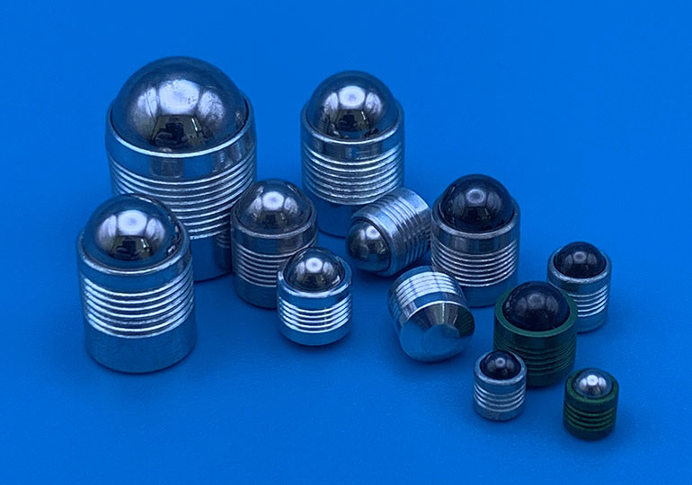
Expander or ball style plugs featured a ball bearing inside of a machined “can or sleeve” plug body. This design originated as a high-pressure permanent sealing option as a permanent leakproof seal.
The installation for low volume applications was done with a set tool and hammer or an arbor press, tapping or pressing the ball down into the sleeve until reaching its final desired position. In higher volume applications operators began to use air hammers to drive the ball into the sleeve, which sped up the installation but does have some disadvantages. Air hammers are very loud and if an operator slips off the ball while installing with air hammers, there is potential for damage to the surface of the manifold, causing scrap rate. The plugs design using a simplified counterbore hole permitted engineers to reduce the size of the applications, decreasing weight (mass), material (cost) and avoided cross threading and need for rework.
Additional increases in pressures as well as intricate designs required sealing experts to design an alternative to the ball style expanders. These ball style plugs ruled the sealing industry for many years until the invention of the rivet style expansion plugs in the late 1980s and early 1990s.
Rivet style plug improve on the design
Rivet style plugs simplified once again the machined hole, needing only a straight bore (+0.12mm/-0) to design these into applications, often resulting in a smaller plug being needed to seal. In addition to the design simplification, the rivet style plugs introduced a hydro-pneumatic installation tool to secure the proper installation of the expander. This introduction virtually eliminated any potential operator error by relying on the tool to break the plug versus an operator pressing the ball to the proper depth.
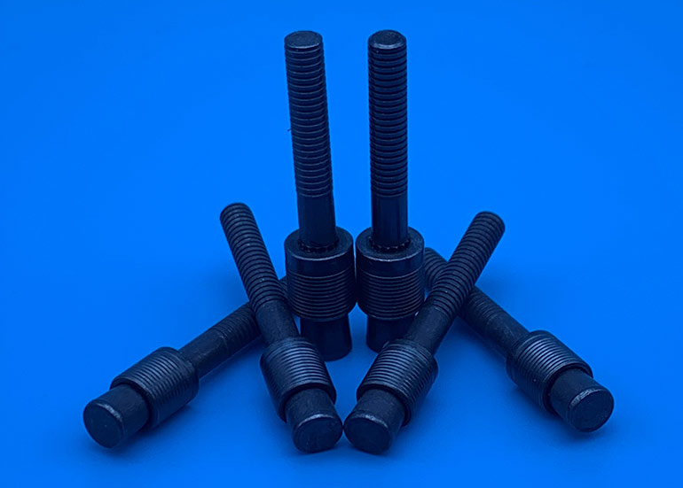
Rivet style plugs needed only a straight bore (+0.12mm/-0), resulting in a smaller plug being needed to seal. The rivet style plugs introduced a hydro-pneumatic installation tool to secure the proper installation of the expander.
Operators easily insert the plug into the hydro-pneumatic tool, present the plug to the hole needing to be sealed, depress the trigger while maintaining flush contact to the surface of material. This allows the internal components of the tool to grab the mandrel while holding the body of the plug just below the surface of the manifold proceeding to draw the pin into the body until the necked down area of the plug reaches its desired break point. At this time, the pin has fully engaged the body causing the necessary radial expansion, sealing the hole at 7,250 psi (at a 3 to 1 safety factor) or 500 bar. Upon the intense and sometimes jolting of the tool necessary to break the mandrel, it is then discharged through the internals of the tool into a collection cylinder ready for disposal. A quick, simple, and cost-effective permanent seal, the rivet style plug was a significant improvement to the expansion plugs as a sealing alternative.
These two options came in a variety of material choices, sizes, pressure ratings, and installation tools and have satisfied hundreds of thousands of customers and sealed billions of holes for more than 30 years. Similar to the ball style plugs, rivet style plugs had room for improvement. The mandrel of the plug which is used to pull the pin into the body, breaks off and is thrown away, essentially scraping 25% of the plug you just purchased.
New benefits with a completely new design
Then came the evolutionary design — the EIS Pull Plug. In 2013, EIS decided it was time to raise the bar. It was then that Brian Krieger, Dave Turechek, and Vic Kirilichin designed, manufactured, validated, and patented the revolutionary EIS Pull Plug.
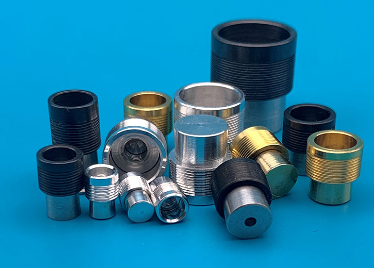
EIS Engineered Inserts & Systems designed the Pull Plug concept to simplify permanent sealing of cross-drilled holes in hydraulic systems.
Uniquely designing away the scraped mandrel of the rivet style plugs and reducing the cost to customer, the EIS Pull Plug uses the spin pull technology to automatically thread the plug onto the tool’s mandrel until ready to insert into the hole for sealing. Placing the expander into the simplified straight bore while the nose of the tool keeps the plug body slightly below flush to the surface of the material, the operator simply depresses the trigger, actuating the tool to pull the pin into the plug body at a predetermined stroke, consistently (not relying on a desired break force to be reached, to separate such as the rivet style plug) causing the full radial expansion then reversing its spin to remove itself from the successfully installed plug. No waste, simple machined hole, fast and secured installation, reducing piece price as well as increasing manufacturing efficiencies makes the EIS Pull Plug the most innovative product the sealing and flow control industry has seen since the inception of expansion plugs.
As EIS developed and introduced the Pull Plug to the market, we continue to find additional benefits of the design. With the mandrel built onto the tooling we can install the same plug at any depth within the manifold by simply using a longer (interchangeable) mandrel and sleeve on the tool. Because our technology uses an internal thread to pull the pin into the body, we have a usable thread that customers can attach wire harnesses, name badges, and the like to. If flow restriction is your need, EIS is happy to drill an orifice through our pin transforming our Pull Plug into a secured restrictor. Manufacturing the EIS Pull Plug in a variety of materials (steel, aluminum, titanium, and stainless steel), sizes (5 – 20 mm) low, high and ultra-high pressure version allows the EIS Pull Plugs to meet the needs in all the following industries: industrial hydraulics, automotive, medical, oil & gas, aerospace, and more.
EIS- Engineered Inserts & Systems Inc.
www.eisinserts.com
Filed Under: Components Oil Coolers, Related Technologies