
Earlier this year, Texas A&M University (TAMU) was named Grand Champion of the NFPA’s 2023 Fluid Power Vehicle Challenge Final Competition. The event was hosted by Norgren in Littleton, Colorado, and held April 12–14, 2023. The competition combined two technology platforms not normally associated with one another — human-powered vehicles and fluid power.
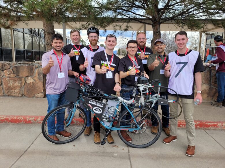
The Texas A&M team designed a bike with a hydraulic circuit instead of a chain to transfer power from the rider to the wheels. Image courtesy of TAMU Fluid Power Club.
The TAMU Fluid Power Club divided its efforts among three teams: mechanical, hydraulic, and electrical. Each team analyzed previous winners’ designs to assess what worked, what didn’t, and what could be improved.
On the mechanical side, the team weighed various bike frame options, including the standard two-wheel bike, adult tricycle, and recumbent bike. Most participants use a recumbent bike with two front wheels and one rear wheel, but some choose two rear wheels and one front wheel. TAMU Fluid Power Club went with a standard two-wheel bike design and brainstormed how to mount everything on it.
“We created a multistage sprocket system going to the pump. We designed the sprockets into their mounts so they could swing a little, and then we could lock them down, changing the chains’ center-to-center distance. That way, we wouldn’t have to design with a specific chain length in mind and could change a sprocket if we wanted,” said Mark Finley, mechanical designer, project manager, and TAMU Fluid Power Club president. “We knew we’d have spacing issues and run into problems, so the design made it easier and gave us some leeway.”
The mechanical team used Autodesk Fusion 360 to model the bike frame and the components.
“As for parts, the NFPA and member companies sent us a list of parts we could request, and then they would send them to us. They also gave us a stipend to buy parts from other sources. We had a lot of design freedom,” said Finley.
On the hydraulics side, the team used Famic Technology’s Automation Studio to simulate hydraulic circuits. The team designed a circuit with four operating modes:
Pedal propulsion mode: Pedaling draws fluid from the reservoir and sends it through multiple T-joints and check valves, a directional control valve, the motor, then back to the reservoir. If pedaling builds up too much pressure, fluid travels through check valve CV2, out relief valve PRV1, and back to the reservoir.
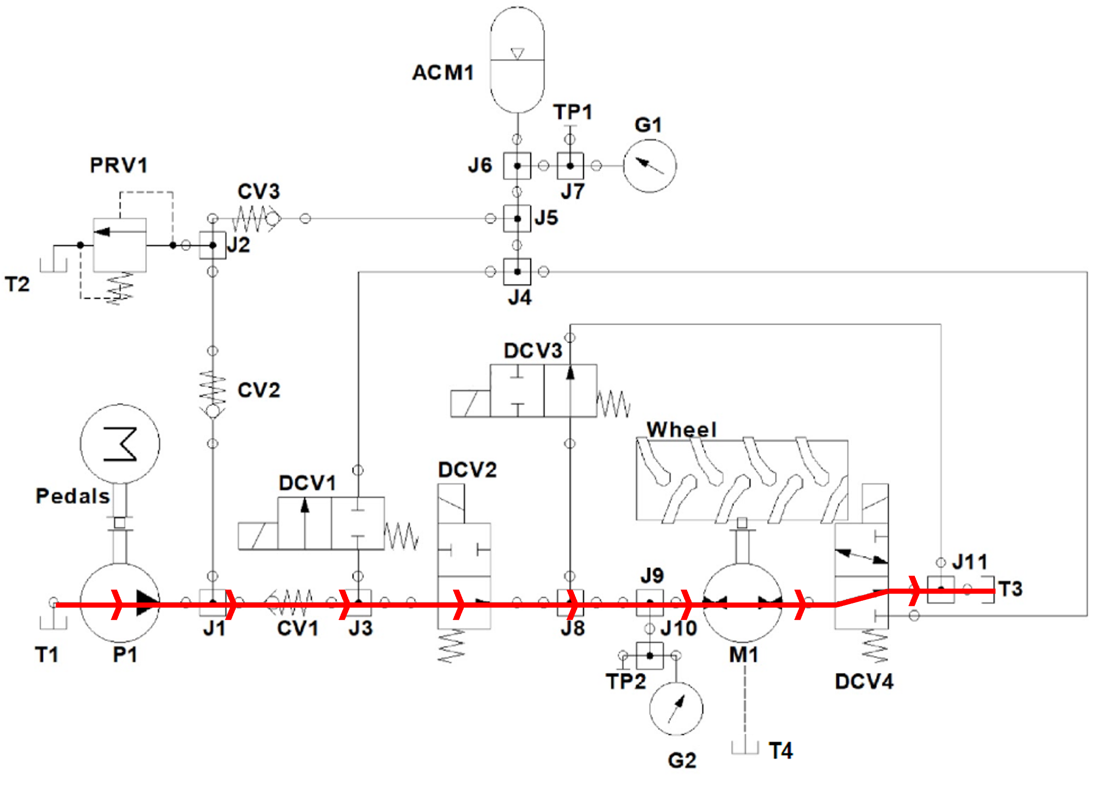
Pedal propulsion mode. Image courtesy of TAMU Fluid Power Club.
Accumulator charge via pedaling: To charge the accumulator, fluid from pedaling routes through directional control valve DCV1 to pressurize the accumulator. At the accumulator entrance, there’s a route to relief valve PRV1 with a check valve to prevent backflow.
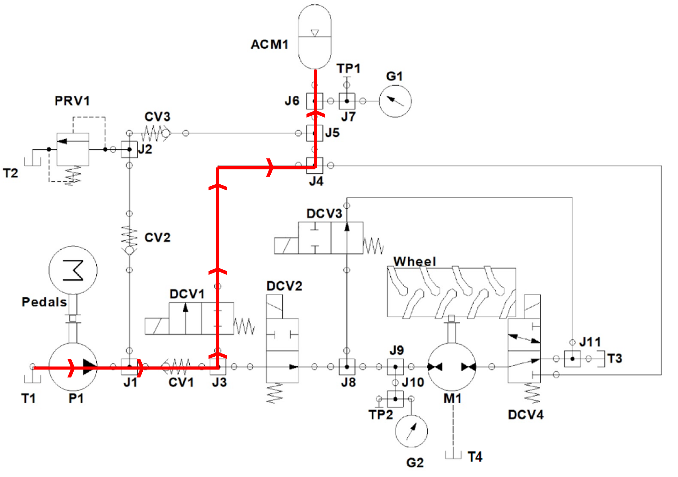
Accumulator charge via pedaling mode. Image courtesy of TAMU Fluid Power Club.
Accumulator discharge propulsion: When using stored energy to power the bike, pressure from the accumulator routes through directional control valve DCV1 to the motor.
Accumulator discharge propulsion mode. Image courtesy of TAMU Fluid Power Club.
Accumulator charge via regenerative braking: The system can also charge the accumulator by reversing the flow direction, drawing from the tank at T3, and moving through directional control valve DCV3 and the motor to the accumulator.
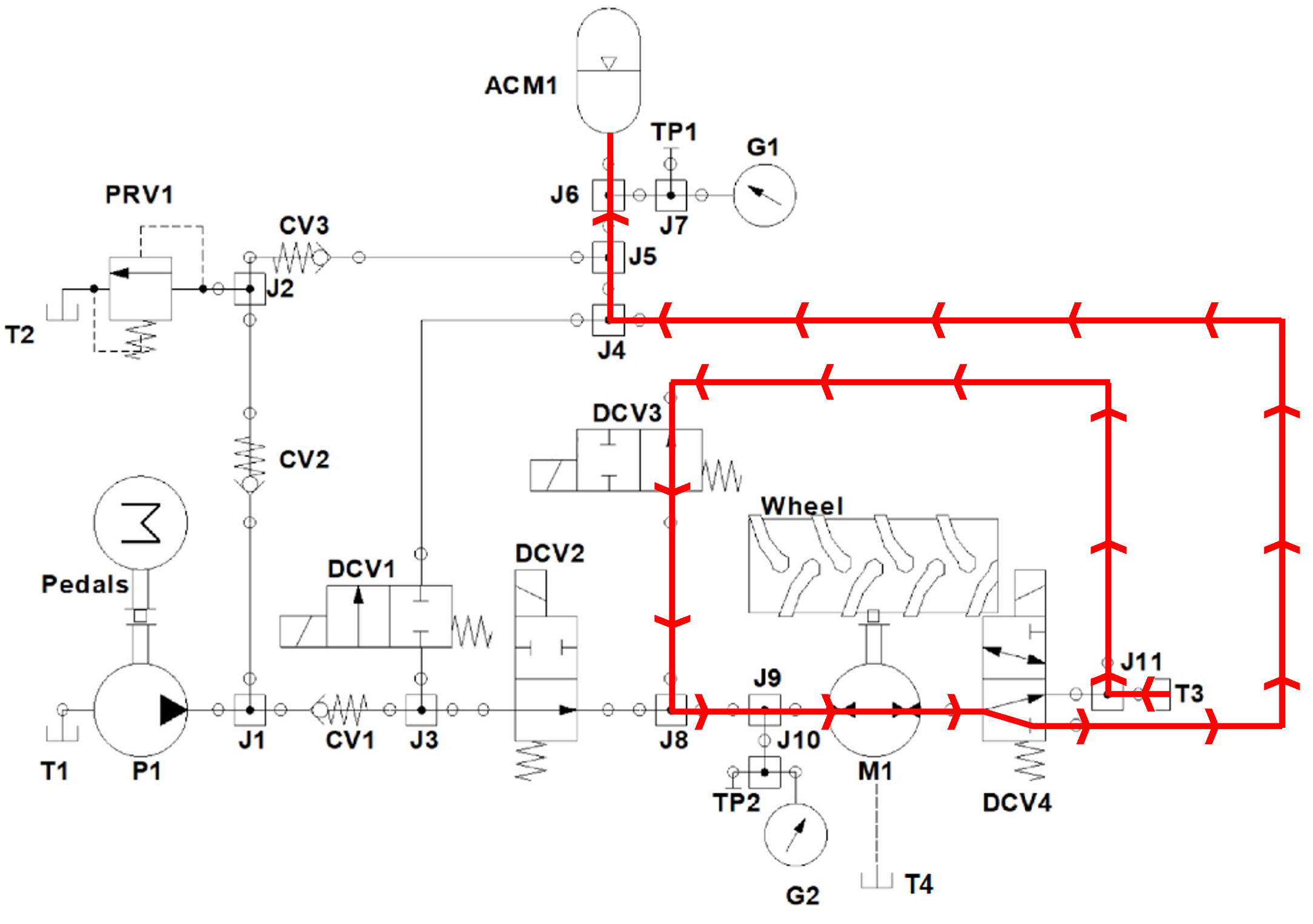
Accumulator charge via regenerative braking mode. Image courtesy of TAMU Fluid Power Club.
The purpose is to ensure that the motor spins in the correct direction.
“When we started testing, the motor was spinning backward. But the problem wasn’t the circuit; it was how we assembled the motor onto the bike — we put it on backward,” said Finley. “So, we had to switch the inlet and outlet. It took some time from our testing, but it was just one of those learning things.”
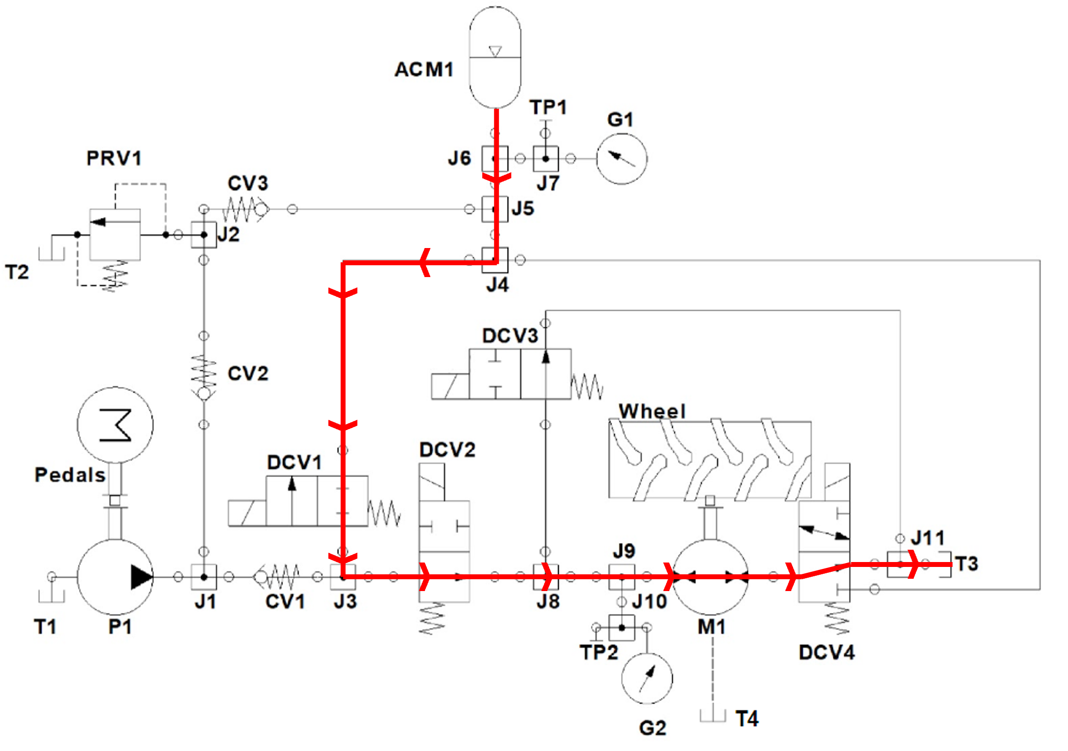
Coast mode: The team wanted to push the bike around or coast down a hill without running the motor dry. So, they designed a coast mode for moving the bike forward and backward. In this mode, fluid is drawn from T3 and flows in a loop through directional control valve DCV3, the motor, and T-joint J11 as the wheel spins. If the system needs more fluid, it can draw more from T3.
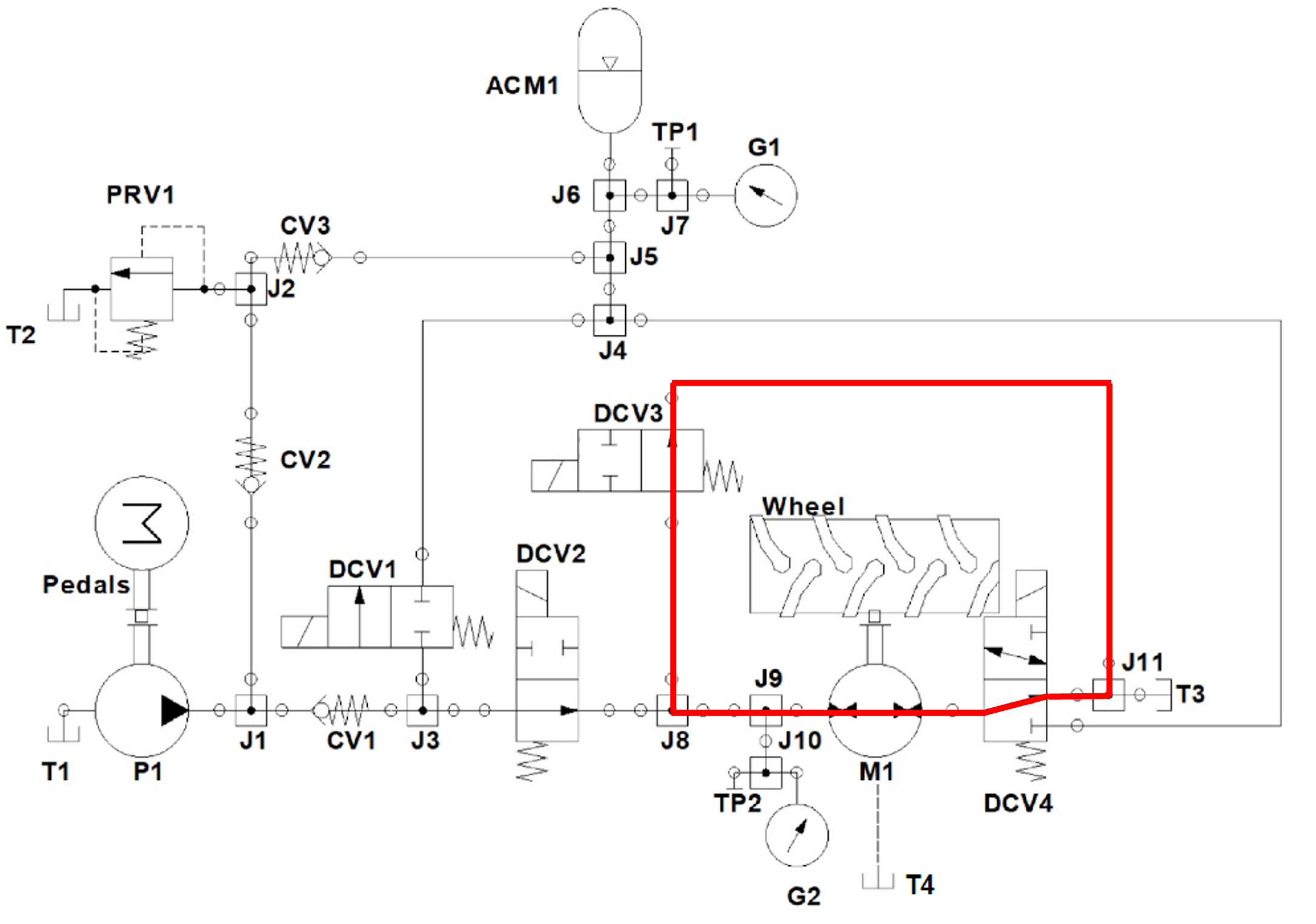
Coast forward and reverse mode. Image courtesy of TAMU Fluid Power Club.
As for the electrical system, the electronics team used a PLC, an HMI screen, and a 24 V battery. The touchscreen HMI includes controls and statuses (on and off) for the four modes and displays accumulator pressure, motor pressure, and pressure trend data. The team installed a safety switch to the HMI mount to activate coast mode if the rider falls off during accumulator discharge.
Before the competition, the TAMU team tested their design to measure how fast and far the bike could travel.
“To test our accumulator, we had to pressurize it with nitrogen first,” said Finley. “We started at around 800 psi of nitrogen and then rolled our bike around in charging mode — we didn’t have to ride it. Then, we tested how far it would go with different nitrogen pressures over equal charging times. We settled on 650 psi, which gave us good distance and speed.”
The bike achieved 16 mph while traveling downhill and on a flat surface.
To win first place, the Texas A&M team competed in four races that tested speed, distance, efficiency, and energy regeneration. The team also won the Innovative Use of Electronics award, sponsored by IFP Motion Solutions. The team earned a $4,000 cash prize for their achievements, of which $2,000 will be used for next year’s engineering technology and industrial distribution department capstone program. The other $2,000 will be split between the team members.
“The team would like to thank the NFPA for the support they provide to be part of this competition,” said Finley. “The big things we all got out of this experience were working in a team, designing, learning about the process, and really thinking through what we make.”
NFPA
nfpa.com
Filed Under: News