
This article is the third in my series on hydraulic symbology, this time going beyond the basics to discuss symbols in higher detail. If you haven’t read Hydraulic Symbology 101 and Hydraulic Symbology 102, please click the links and read them first to gain the basics required for this article. If your basics are sound, however, carry on learning the intricacies of industrial directional valve symbology.
I’m separating the lessons on directional valves between industrial, mobile and cartridge valve technologies. Each uses symbology differently because their valves are manufactured and applied individually based on the needs of their industries. Through-center valves are not used with industrial applications, and 3-way valves are only common with cartridge valves, for example. This article covers the basics of industrial valve symbols, while Hydraulic Symbology 202 will cover the compound symbols used with industrial stack valves.
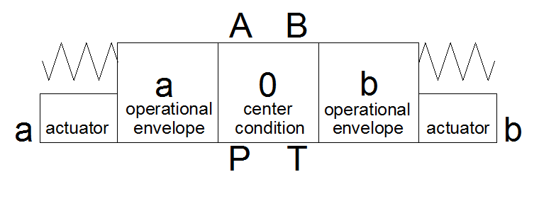
The above symbol shows the typical 3-position directional valve with the internal lineation removed. Each of the square boxes depicts one of the three functional envelopes of which the valve is capable. The center condition is referenced as position 0 because it’s the natural valve state prior to any actuation. The center condition is important to consider because the type of pump needed is dictated by center flow conditions. If the valve allows flow in neutral, a fixed displacement pump is ideal, while a center condition blocking incoming flow requires a pressure compensated, variable displacement pump.
Want more symbology content? Download our 45-page Symbology Building Blocks e-book now.
The remaining two squares depict the operational envelopes of the second and third valve positions, which are the functions of the valve. Envelopes are referenced with a or b to define the envelope pertaining to the given actuation method. The reference can be located on either side of the valve symbol, and is generally manufacturer specific, so ensure you use their documentation when interpreting symbols. What matters is that the a actuator operates the a envelope, for example.
The valve ports are listed both above and below the center condition envelope. This not only provides clarity on the port locations, but also defines the at-rest position of the valve. For example, a valve may not have a neutral center condition, but could be at rest in the a or b envelopes, such as with a 2-position valve. Regardless, I’ve only ever seen the display order of A B on top with P T underneath.
The actuators, in function, are the electric or mechanical devices that shift the valve out of neutral to any of the operational envelopes. There are myriad actuators, although with electronic technology advancing so quickly, the forms of mechanical actuation are becoming rarer. Electric solenoid operation is by far the most common for industrial valves, and is depicted by the same basic actuator rectangle with a diagonal line. Although a line leaning to the left is meant to represent the coil pulling on the plunger, the right-leaning line showing a coil pushing on the plunger is more common, regardless of axial direction.
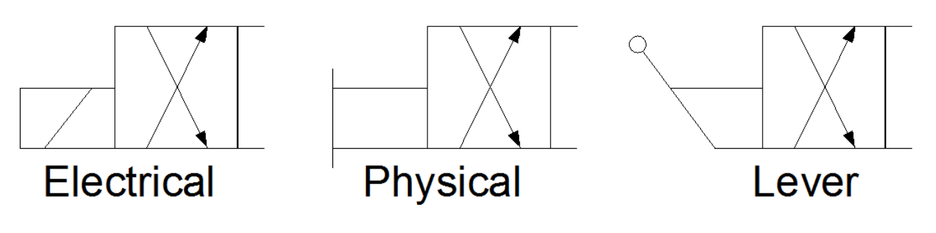
The blunted actuator representing a physical actuation is the most generic representation of manual operation. This symbol can technically represent any form of physical actuation but is non-descriptive. It’s preferred to reserve this for only the manual override of a valve, and is often used in conjunction with the solenoid operator (see below). For the strictly manually operation, the lever actuator makes sense, and can be seen in forms varying from the one above.
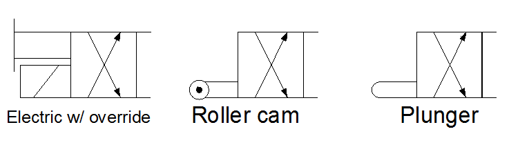
It was previously common to do factory automation by way of directional control valves, but the practice is less common in the current electronic age. However, you may still come across roller cam or plunger valves. The roller cam is ideal for actuating a valve as a device moves perpendicular to the cam, pushing it down and switching the valve. You can imagine this valve creating a functional series, as the extension of one hydraulic cylinder at the end of stroke can actuate the next function. The same can be said of the plunger valve, which is similar to the cam function but meant to accept only axial force against the plunger.
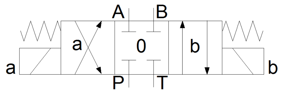
Above is the same valve as previously shown, but with the internal lineation replaced. This is a complete hydraulic symbol showing a closed-center, 4-way, 3-position, spring-centred solenoid valve. In the at-rest position, all ports are blocked and the only flow that occurs is the result of leakage. The pump will be variable displacement or with some sort of automatic unloading function. Flow to and from the actuator will be blocked, but because of the leakage I mentioned, you wouldn’t use this for load holding. Firing the a coil would provide flow paths from P to B and A to T, while firing of the b coil would allow flow from P to A and B to T.
Other common center conditions for valves are shown above. The float center spool is used in circuits where both work ports are required to be open to tank while in the neutral position. It is used in conjunction with load holding or motion control valves, which themselves necessitate draining of their spring chambers, a function that wouldn’t occur with a closed center. These spools are also called motor spool because they allow fluid to pass through the center of the valve from one port of the motor to the other. This operation allows a motor to spin down naturally under its own energy, rather than an abrupt stop as would occur with a closed center. The float center spool has its P-port blocked, so pressure compensated pumps are needed.
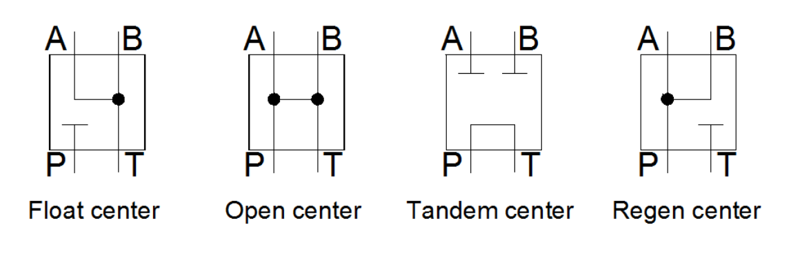
The open center valve provides the same benefits as the float spool, but can be used with fixed displacement pumps. The pump flow is naturally unloaded to tank, and the spool also provides a drainage flow path for any accessory valves attached to the A and B work ports. The tandem center valve is also used for fixed flow systems where fluid is unloaded to tank in neutral and work port flow is blocked. This spool is common on gear pump systems operating cylinders with no work-holding requirement. Less common but worth mention is the regen center valve, which opens pump flow to both work ports simultaneously. This counterintuitive function allows a differential cylinder to extend with twice the speed at half the force, and can be controlled electronically or hydraulically to provide full or part-time regeneration. There are dozens of other center conditions for spool valves, but these five make up ninety percent of what you’ll come across.
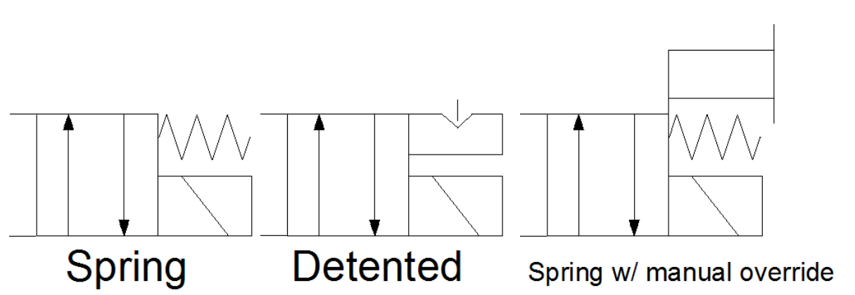
There are auxiliary functions to every directional control valve, and these add utility to the valve. The spring is used to center a 3-position valve, or to offset a 2-position valve. When no power is applied to a coil, the spring force is sufficient to center the valve to its at-rest position. Some occasions require that a valve is left in an actuated state without any physical or electrical motivation to maintain position. A detent mechanism can be added to either side of a valve to create maintained flow such as is required for some motor or clamping functions. The manual override can be added to nearly any directional valve symbol, but when real estate is limited, this function is typically added above the others, as shown. The method of physical override is not spelled out, and could occur through knobs, handles or even hidden buttons.
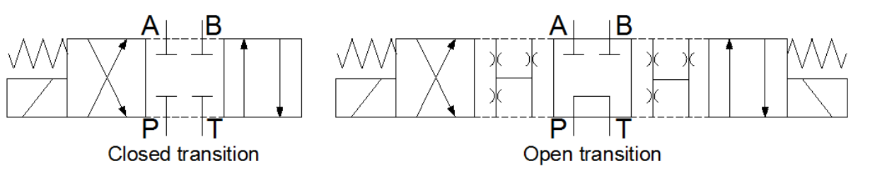
If you look at the above symbols, you’ll notice something odd if you’re not deeply familiar with symbology. How is it possible to have three distinct positions with a single coil? For that matter, how is it possible to have five distinct positions in any valve. The symbols here depict spool transitions. The closed transition example is actually a 4/2 single solenoid valve, but if you look closely you can see a dashed lined in the center envelope.
The dashed line in directional valve symbology illustrates the transition of a valve; it’s the functional action of the valve as the spool moves from being solid against the valve body, to partially open and finally fully open. What happens in between has consequences on system performance. The closed transition shows us this valve has no metering as it switches from P to B & A to T and then to P to A & B to T. Flow simply stops abruptly, and then restarts the opposite direction.
In the open transition example, the valve spool has a metering effect at all ports before finally providing the directional function as listed above. Starting in neutral with P to T flow while the work ports are blocked, if we switch to the left side envelope, A, B & P are metered into the center while the tank line bleeds directly to reservoir. As the spool shifts fully, P flows to B while A drains to T. This spool shifts smoothly, but because fluid has a temporary path to tank during transition, you must be careful to use load holding, if required, since the downstream actuator can drop its load for a fraction of a second.
Next time, I’ll discuss the methods of building pilot operated and stackable valves. Pilot operated valves are required for system flows above 30-40 gpm, and these valves can be illustrated two ways. Modular stack valves are a method of creating complete circuits using CETOP ISO valves, but their symbology is different from normally drawn circuits.
Filed Under: Fluid Power Basics, Slider, Valves & Manifolds