
Innovation in pneumatics is often found in the way components are put together to create subsystems, instead of within the components.
Contributed by Pat Phillips, PE, Product Manager for AutomationDirect, Fluid Power and Mechanical Product Div.
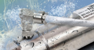
Pneumatic components in food, beverage and pharmaceutical plants must often meet washdown requirements. All images courtesy AutomationDirect
Pneumatics have been used in industrial machines and manufacturing plants and facilities for decades, so most of the basic components are tried and true, with significant innovations few and far between. But, there are many innovative ways to combine these different components to produce pneumatic subsystems.
This article will look at four pneumatic subsystems (Table 1), and will show how combining basic pneumatic components in novel ways improves operation, maintenance and safety.
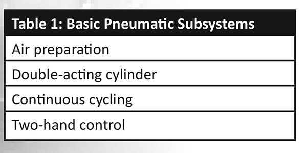
Table 1- Basic Pneumatic Subsystems
The first subsystem we’ll look at is air preparation, appropriate because air should be prepped before it is used in any other subsystem.
Air preparation subsystem
A single-point pneumatic air connection should be used on most automated machines, starting with an air preparation subsystem as depicted in Figure 1, with its components listed in Table 2.
A fairly recent innovation is combining some or all of these components into one unit, which can be purchased from a vendor with a single part number. This is often much more convenient and cost-effective than buying individual components and assembling them into a unit.
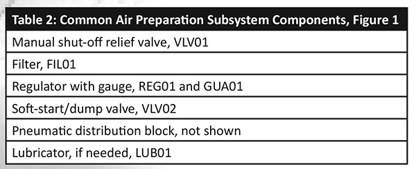
Table 2-Common Air Preparation Subsystem Components
While the order of these pneumatic devices in an air preparation subsystem is debatable, a good design practice is for the first component connected to the plant air supply to be a machine-mounted, manual shut-off relief valve, or a pneumatic isolation/lockout valve. This valve removes the supply of all compressed air from a machine for servicing, and relieves downstream pressure at the machine. Although not shown in Figure 1, the manually rotated shut-off knob can be locked in the off position.
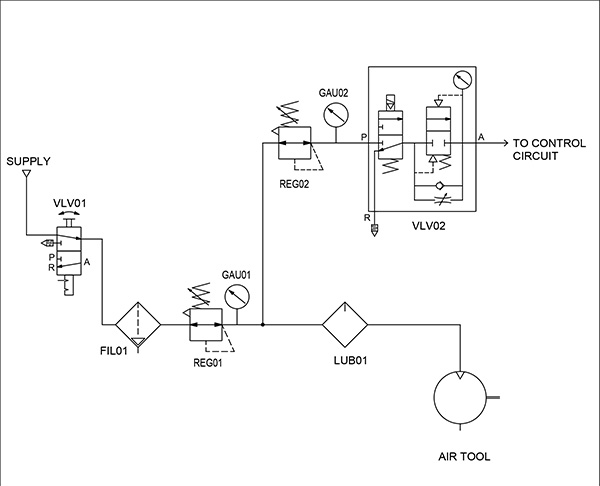
Figure 1. Air prep circuit diagram: This air preparation circuit, often called an FRL (filter, regulator, lubricator), is commonly used on many machines, and its use is recommended as a good design practice.
If the shut-off valve is mounted downstream of a filter, as in some installations, filter service is difficult. If dirt and debris are a concern upstream of the shutoff valve, the filter can be installed upstream of the valve instead of downstream, but it will be necessary to install a 3-way shut-off ball valve with a muffler in the compressed air system supply pipe to safely remove air. This valve provides an alternative to shutting off all plant air pressure to change a filter.
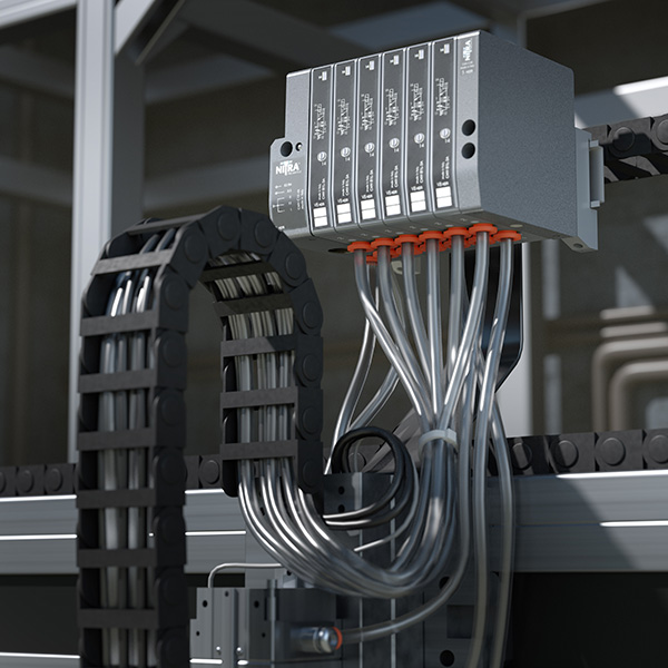
Moden compact valve manifolds are an excellent choice for factory automation applications because they take up less space and simplify installation.
Downstream of the shut-off valve is a filter to remove particulates and separate moisture from the air supply. The triangle at the bottom of the filter symbol indicates it includes either a manual, semi-automatic or automatic liquid drain. The type of bowl, such as all-metal, is not indicated on the figure, but a pneumatic panel layout drawing may include this information, as well as mounting brackets.
The regulator is next in the air flow and it is good practice to note the maximum pressure and working pressure range in the circuit diagram. A pressure switch, not shown in Figure 1, can be included in the air prep subsystems to monitor pressure just downstream of the regulator.
The triangle symbol at the upper left corner of REG01 and REG02 indicates the regulator is a relieving type. A good design practice is to always use a relieving-type regulator to ensure pressure is removed downstream of the regulator when upstream air is exhausted. When installing, air flow direction is important because regulators have input and output connections.
The clean, filtered air exiting the first regulator is split through a pneumatic distribution block, not shown on the diagram, to supply an unlubricated and lubricated air supply. The electrically operated soft-start/dump valve is usually the last device before air cylinders, actuators and other motion-causing pneumatic devices, which typically don’t need lubrication. It provides a means to dump motion-causing air pressure when an emergency stop is activated. A lubricator is often installed in the air supply line to air tools.
Double-acting cylinder subsystem
Figure 2 depicts a 4-way solenoid valve (SOL01) controlling a double-acting cylinder (CYL01). This is one of the most common pneumatic functions on an automated machine controlled by a PLC. The air supply to the solenoid has already been filtered by the air preparation unit.
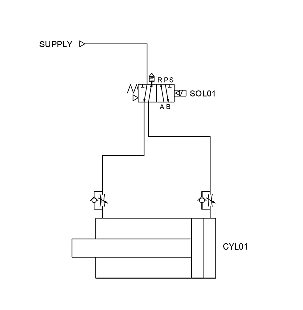
Figure 2. Double-acting cylinder circuit diagram: Double-acting cylinder circuits are typical on many PLC-controlled machines.
The valve solenoid symbol indicates a single-acting, spring-return valve. The triangles in each side of the valve indicate it is pilot-activated as well. While this pilot air makes the valve more efficient, it also requires a certain amount of pressure. For example, supplying less than 20 psi can stop the valve from functioning, so users should check the valve specifications for minimum operating pressure.
The spring on the left side of the valve pushes the valve spool to the right when the solenoid is turned off. This supplies air out of port A that free flows through the flow control to the left side of CYL01, causing the cylinder to retract. While retracting, air on the extend side of the cylinder is exhausted through a flow control device, then through port B on the valve to a muffler at port S.
When solenoid SOL01 is energized, typically by a 24 Vdc PLC output, the valve switches, supplying pressure out Port B, which free flows through the flow control to the extend side of the cylinder. It may be helpful to imagine the circuit symbol sliding to the left, to understand the air flow paths when the valve is energized. As the cylinder extends, the air exiting the retract side of the cylinder is controlled through the flow control device, and then exhausts through port A to port R, and finally through a muffler.
Continuous cycling cylinder subsystem
Figure 3 illustrates how pneumatic components can be combined in an innovative fashion to create a continuous cycling cylinder. No electronics or PLC is required with this novel design, just compressed air supplied to valves VLV02, VLV03 and VLV04.
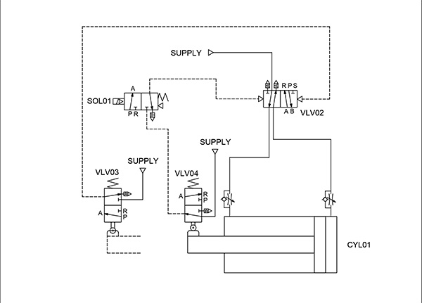
Figure 3. Continuous cycling circuit diagram: This continuous cycling cylinder circuit shows some of the control capabilities of pneumatic components.
To start the system cycling, with CYL01 physically retracted, SOL01 is energized to provide pilot air to VLV02, a directional control valve, which extends or retracts the cylinder, similar in method to the double-acting cylinder discussed above. One-way flow control valves are used to control the cylinder speed by controlling the air exhausted out of the cylinder.
When the cylinder extends, it operates VLV03. This supplies pilot air to VLV02 switching its position and reversing the direction of CYL01, retracting the cylinder. Once retracted, the cycle repeats if SOL01 remains energized. The design of this pneumatic circuit ensures that when SOL01 is de-energized, the cycle always ends with the cylinder retracted.
Key components for this pneumatic logic are the 4-way air-piloted valve (VLV02), and the two 3-way roller-actuated valves (VLV03 and VLV04). Instead of springs and electrical solenoids controlling the position of the valve spool, air pilot pressure alone operates VLV02. The roller-actuated valves, configured like the mechanical arm on a limit switch, actuate VLV03 and VLV04, each of which is spring-returned when not actuated. Cams or flags on the cylinder actuate the valves.
Two-hand control subsystem
Figure 4 depicts a two-hand safety control circuit for a press application. This circuit provides a good example of the inventive use of manual 3-way valves (pneumatic buttons, VLV01 and VLV02), and an air-piloted 4-way valve (VLV03). The design of this circuit allows small manual valves to operate a large pilot-operated valve with high air flow requirements to drive a large press cylinder. This circuit does not include anti-tiedown checks or control reliable design, which may be needed for safety.
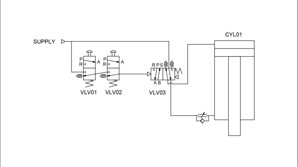
Figure 4. Two-hand control circuit diagram: This two-hand control circuit shows how manual pneumatic buttons can be used to improve safety when operating heavy machinery such as a press.
The design of this circuit requires the operator to press both buttons simultaneously. Once this is done, pressure is cascaded through the two hand valves, supplying pilot air to actuate the 4-way valve. When activated, the double-acting press cylinder (CYL01) extends. The use of a 4-way, spring-return valve retracts the press cylinder when either button is released to its normal, relaxed position as air is supplied to the retract side of the cylinder.
A one-way flow control valve throttles the press cylinder extend speed. A second speed control could be added to regulate the air exiting the cylinder and the retract speed. It may be necessary to flow control air into the cylinder instead of out of the cylinder if all air from a cylinder is exhausted during normal operation.
An air regulator, not shown, can also be added to control press force. This press force can be monitored with a pressure switch, also not shown. This pressure switch could provide an input to a PLC to indicate press force attained for error-proofing purposes.
These four pneumatic subsystems show some of the functionality available by combining common pneumatic components in innovative ways. Additional combinations can be used to create other subsystems, limited only by the imagination.
AutomationDirect
automationdirect.com
Filed Under: Pneumatic Tips, Slider