
Fluid Power World Contributing Editor Josh Cosford gave a webinar presentation on Proper Hose Assembly Guidelines. The transcript has been divided into an 8-part blog post series. The following excerpt from that webinar transcript is the sixth part of the series.
Ends are literally the fittings that you’re going to be attaching to the hose itself. Lots of things to consider here. It’s really application specific. It could be geography specific; if you’re in North America, you’ll have different threads than if you’re in Japan or Europe. Is your hose going to have male or female threads? And that’s going to depend largely one what exists on the machine already or what you can put there.
Is there a reason you might use a swivel? Could it be a swivel-on, like a JIC that swivels until it locks? Do you need a live swivel? Does the machine bend as well as pivot? If you have something like a grapple that might bend if you need one hose, that has a live swivel.
Also, should you have straights or elbows? This is going to depend a lot on how the hose lies. If you have a hose coming perpendicular from a machine so that the gravity wants to pull down on the hose, that puts a lot of stress on the joint, especially right were the hose meets the fitting. You want to have a 90° fitting to let that hose take advantage of gravity so that it goes vertical with the machine, not stick out perpendicular to it. And whether you want permanent or reasonable fittings; these are two things we’ll discuss certainly.
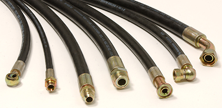 Here’s the general selection of hoses you might see with pretty much any fitting that exists in hydraulics or any machine. Starting from the far left you have a banjo bolt. Next to that, it looks like you have a metric, or could be BSVP, but probably metric. Third from the left is a male JIC, then you have a flat-face coupler. Next to that you have what could be a code 61 or 62 flange, a C flange; it’s also a face-style coupler. Next you have a 90° coupler; that one could also be a JIC or MPT. The far one on the right, that’s actually a swivel MPT fitting. That one would go on to a male end swivel-on so that you didn’t have to twist the whole hose around.
They’re also reusable fittings. These are some fittings that you can use in the field. They also call them field attachable, but the crimped-on fittings are permanent. Sometimes the field attachment ones are needed in the pinch. You can’t really get around it. Most often, if you can, the crimped-on fittings are the most reliable. They’re crimped-on and fairly permanent. Vibration or heat cycles aren’t going to let them come loose like you can with a reusable fitting.
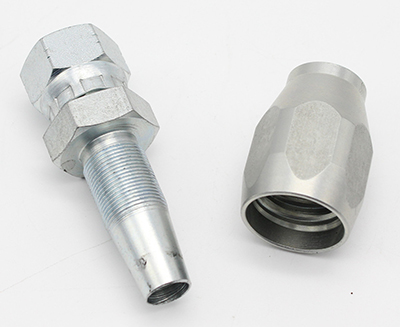
Reusable Hose Ends
Pictured to the left is a reusable hose end. The piece on the right gets threaded onto the hose. You can picture that the hose comes in from the close end, you thread that on, it goes onto the hose. The teeth on those threads dig into the hose carcass and lock it in place. Then you insert the left-side piece inside the hose. The threads would engage and as you tighten it down, it would compress the hose outward into the teeth of the right-side piece. This allows you to install a hose in the field.
They get pretty tricky to do. You usually need a vice to do these. When I used to use a reusable fitting, I used an impact gun to assemble. There’s a lot of work involved. It’s a pretty high torque application, and I wouldn’t want to do these with hand tools. You can put a lot of stress on your wrists.
Crimped ends, you can get these in 1 or 2 piece. Depicted in the image below are pre-assembled one-piece style fittings. You just slip on the hose, insert into your machine and crimp away. You have a selection there, pretty self-explanatory. Also, consider what kind of crimping machine you want to use. We’re getting past the hose selection phase and working on what it takes to actually crimps a hose.
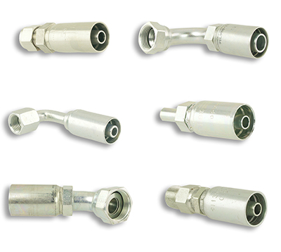
Crimped Hose Ends
The post Proper Hose Assembly Guidelines, Part 6 – End Selection appeared first on Hose Assembly Tips.
Filed Under: Hose & Tubing, Hose Assembly Tips