
Fluid Power World Contributing Editor Josh Cosford gave a webinar presentation on Proper Hose Assembly Guidelines. The transcript has been divided into an 8-part blog post series. The following excerpt from that webinar transcript is the second part of the series.
The STAMPED acronym stands for size, temperature, application, material, pressure, hose ends and considerations for delivery. We’re going to start with size. The size considerations you need are the ID, the OD, and the length. Hose must be sized appropriately to handle flow with little pressure drop.
OD is critical if you’re passing your hose through bulk heads or if they’re being clamped on hose clamps and stuff like that. If you have a 1-, 2-, 4-, 6-wire hose, the more layers of braiding in there the thicker the hose is going to be and that could affect how something is clamped down. OD is important for application.
Considering the ID of a hose, if you have a particular flow rating that you need to accommodate, you need to have the internal bore of that hose large enough to handle the fluid flow with little or no pressure drop. You have to keep in mind that the longer the hose the more friction or the more pressure drop that will be created, the more back pressure. That goes up exponentially as you decrease the size of your hose. For example, if you had a 2-in. hose and you reduced it to a 1-in. hose, you’d have 4x the back pressure, not twice the back pressure. Also, if you have a long length of hose, you also have special considerations for ensuring there’s less back drop, back pressure especially running 5, 10, 20 ft, things like that. You may need to up size the size of your hose to accommodate the flow that you have in your system.
There are lots of resources you can find online. There’s normal graphs or flow calculators and things like that. If you’re not sure how large your hose should be sized for any given flow or length of tubing, find one of those online calculators or normal graphs because the selection depends on if you have a suction line, if you have a pressure line, if you have a return line. They all vary from each other and require different sizes of hoses.
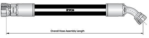 Also, consider measured length from tip to tip. The image above shows the overall hose assembly length. We generally don’t measure from tip to tip of the hose. This one has 2 JIC fittings on either end. One is a straight on the left side and the other is a 45. We’re not measuring tip to tip on the fittings for a couple of reasons. If you have a JIC male on either side of the assembly and you measure from tip to tip of those fittings the hose may be too short to actually be threaded onto the fittings.
If you look on the left side with the straight fitting, the length is measured at the seat of the JIC. The part with the hose fitting on the left actually fits against the JIC male part on the machine. On the other side we’re going to measure on a 45, so at the center point of the fitting. You can see that it goes right through the center. It doesn’t measure to the tip on the corner. It doesn’t measure to the leading edge. It measures right in the center. This is what we call your overall hose assembly length. This is the critical part to remember. It doesn’t matter what kind of hose you have. You want to measure where the fittings are, not where the tips of the hose are.
Thirdly, when it comes to hose length, we also want to cut the hose to a particular length. Depending on what manufacture of crimp fittings you have, you can vary on what your actual hose cut length is based on what those fittings are. Every manufacturer is different and what you’re going to have is something called “the cut off length” added to your fittings.
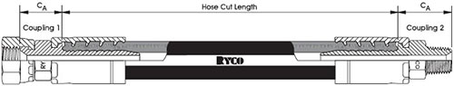
You can see on the right side we have an MPT fitting and we are going to consider the entire length used there from the tip of the MPT right to where the hose stops inside the fitting. You can see that through the cutaway where the Ts grab into the hose and then that CA dimension on coupling 2. Also, when you go to the other side of the JIC fitting, that CA fitting stops at the seat of the JIC and then over to where the hose stops inside the ferrule.
Those CA dimensions are critical to know because once you have your finished hose length you want to achieve, you have to find the hose fitting that you’re using in a catalog and reference material for that particular hose fitting manufacturer, in this case RYCO. It could be Gates, Parker or Eaton or whatever. Whatever they are they will have information available to you. You subtract that cut off length and that will allow you to have the finished length of your hose.
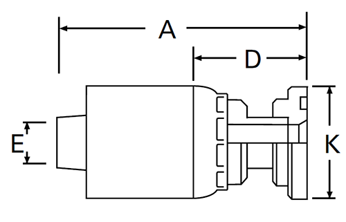 This a flat face fitting uncrimped. That cut off factor in this case would be the D in the picture to the right. That’s the number that you will subtract that will be in the catalog, so that the entire hose length subtracted by 2D in this case, 2x this on the other end, is what you’re going to cut your hose to.
The post Proper Hose Assembly Guidelines, Part 2 – STAMPED appeared first on Hose Assembly Tips.
Filed Under: Hose & Tubing, Hose Assembly Tips