
What is a cleanliness code chart?
Cleanliness is not a subjective term, but rather a specific quantitative value. Therefore, a cleanliness code chart is a tool whereby a person responsible for the usefulness and longevity of a machine can set a value for ensuring their hydraulic fluid is clean.
“The purpose of the code is to standardize and simplify a method for counting the particles in system fluid. To put it simply, it tells the equipment user how clean their fluid should be for the best life and uptime of their equipment,” Brad Poeth, North America Training Manager at Eaton Corp, explained.
What is the basis of a cleanliness code chart?
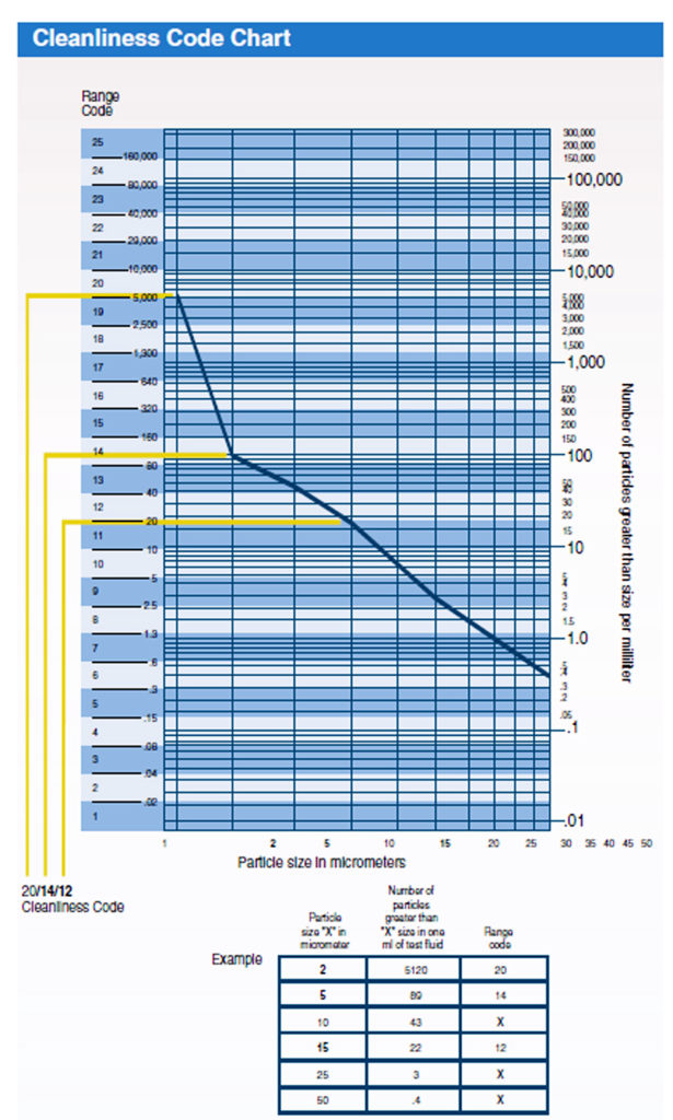
“The chart in use today has evolved over the years,” Poeth said. “As technology has improved, so have the charts and the accuracy of particle counting. The latest standard was created in 1999. The code that comes from the chart in use today contains three digits, the first representing 4 micron particles and larger, the second digit representing 6 microns and larger, while the last digit represents 14 microns and larger.”
“These scale digits represent the number of particles each size and greater, contained in one milliliter of fluid. For example, the number 20 means that there are 5,120 particles in one milliliter of fluid. The number 21 represents 10,240 particles, so the number of particles will double as the digit increases by one.”
What do you need to consider when creating a custom cleanliness Code Level from the chart?
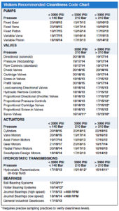
When creating a custom cleanliness Code Level from the chart, Poeth say that it is important to consider the type of equipment being used (i.e. how sensitive the component is to contaminated fluid), the pressure it operates at, and what type of fluid is being used. “Of course, other factors may also impact the fluid cleanliness Code Level, such as frequent cold starts, high temperatures, vibration, and so forth,” he said. “The key word here is ‘custom’. Every operating detail must be taken into consideration to make a truly effective custom fluid cleanliness Code Level.”
“The benefit is that when using the proper cleanliness Code Level and understanding the selection of the code from that chart, the person responsible for the machine has a better idea of how clean the fluid must be for optimum life and uptime, greatly helping to achieve target cleanliness.”
Where does the contamination come from?
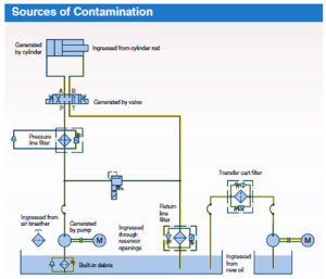
Knowing contamination sources is also important. Poeth notes that there are four primary sources of contamination: new oil, built in, ingress and generated.
“New oil should always be filtered before being used,” he said. “While refiners take care to process and blend formulations in a clean environment, when you take into consideration how many times the fluid is handled, transferred, and so forth, the opportunity for the fluid to become contaminated is high.”
 “Also, new machinery always contains a certain amount of built-in contamination. While care in system assembly and in new component flushing reduces, but never eliminates it. Typical built-in contaminants are burrs, chips, flash, dirt, dust, fiber, sand, moisture, pipe sealant, weld splatter, paint and flushing solution, to name only a few.”
“Ingress contamination refers to contaminates from the environment that find their way into the system. The key to avoiding this is to severely limit the access environmental contamination has to enter the hydraulic or lubrication system. There are four major ways dirt can enter a system: reservoir vent ports (breathers), power unit or system access plates, components left open during maintenance and cylinder rod seals.”
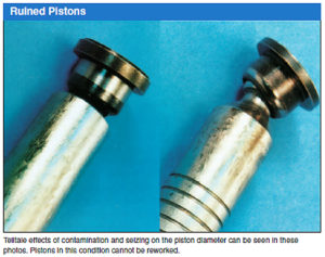
“Finally, the most dangerous contamination to a system is the contamination generated by the system itself. These particles are ‘work hardened’ to a greater hardness than the surface from which they came, and are very aggressive in causing further wear in the system,” Poeth said.
How to extend system life
In conclusion, a clean system is always the ultimate goal. Poeth says that in a system running on properly cleaned fluid, very few particles are generated, although all components (especially pumps) create a small amount of particles during routine operation.
 “The issue to be aware of is that in a system where these particles are not quickly captured, the elevated contamination levels will cause the number of additional generated particles to increase at a highly accelerated rate! The best way to prevent contamination generation within a system is to start with a clean, fully flushed system and keep the system fluid clean. A clean system makes for a happy plant; lower maintenance costs, more up-time and longer machine life.”
–By Joyce Laird
The post How do you use cleanliness code charts? appeared first on Sealing & Contamination Control Tips.
Filed Under: Filtration/Contamination Control, Sealing & Contamination Control Tips