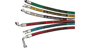
In this three-part series, the author will discuss how hose tubing and routing can simplify maintenance and reduce hose failure.
By Mike P. Beining, Product Manager, Eaton
The failure of high-pressure hydraulic hoses or tubing is responsible for high costs resulting from lost productivity, negative environmental effects, collateral damage and most importantly, safety. By using correct routing techniques and advanced technologies like Eaton’s LifeSense Hydraulic Hose Conditioning Monitoring System, the frequency and impact of hydraulic hose or tubing failures can be significantly reduced.
 In hydraulically controlled and actuated machines, some components cannot be altered as their locations are controlled by the structure of the machine. However, other components can and should be placed where they are easy to connect, readily accessible and convenient to service.
System designers should endeavor to eliminate as many fluid conductors as possible by using manifolds to interconnect components. In most cases, external piping must be used. Minimizing potential leakage points and making maintenance as simple as possible should be the goals of any astute designer. When designing the basic machine, engineers should remember to:
- Provide adequate space to route hose and tubing
- Coordinate hydraulic system planning and design with other systems on the machine; i.e. electrical, fuel, lube, torque converter, etc.
Coordinate hydraulic system planning and design with other systems on the machine; i.e. electrical, fuel, lube, torque converter, etc.
Parallel routing
Whenever possible, hydraulic lines should run parallel within the machine envelope and follow its contours. Smooth, parallel routing can be accomplished with a well-planned layout and proper clamping. To help keep lines parallel, study port positions on components and, carefully pre-plan the location of valves, filters, heat exchangers and reservoir.
Parallel routing can often save money by:
- Reducing line lengths and the number of adapters used
- Minimizing the number of sharp bends
- Making the machine more serviceable
- Protecting lines from external damage
Components should also be spaced far enough apart to provide room for proper installation of the adapters and fittings on connecting hoses and/or tubing.
Hose and tubing
System designers must first determine whether using hose, tubing or a combination of the two is best for a particular application. Hose and tubing should be viewed not as separate entities, but as companion items, each offering specific and unique benefits. For example, tubing can:
- Be bent to smaller radii than hose and installed in tighter spaces
- Be routed through areas of higher ambient heat
- Handle hotter fluids than hose
- Provide superior heat transfer characteristics
On the other hand, tubing can be flattened or damaged when struck, whereas hose is resilient and more likely to return to its original shape after absorbing a blow. Tubing may also fatigue when connected to high frequency vibrating components, while hose will absorb the vibration.
Where lines are long, tubing may require a series of intricate, close-tolerance bends that may complicate installation and ultimately create service problems. The flexing properties of hose, on the other hand, allow it to follow desired contours and make hose installation easier. Hose can also absorb some high transient pressure shocks, providing more uniform flow patterns and smoother, quieter operation. Hose is not recommended when hydraulic rigidity is required due to its tendency to act as an accumulator.
Eaton
www.eaton.com
Filed Under: Hose Assembly Tips