
Manifolds are unique to each machine they run, making designing and building the right manifold a complicated task. Ask any manifold designer or distributor – there’s no such thing as building the right manifold on the first try.
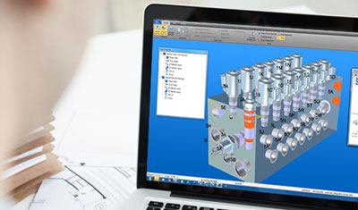
Since the introduction of manifold software, the design and build process has gotten significantly easier. More 3D design tools are available than ever before. making it possible to build the initial design in 3D and removing the need to visualize a 2D design in 3D as part of the design process.
Consider the design process. An original equipment manufacturer (OEM) would approach a manifold designer, looking for a circuit that does X and a manifold that accomplishes Y. The designer begins to lay out the manifold, adding the valves and considering the options.
The first version of the manifold is sent, but while the initial design is being developed, the pressure on the machine has changed, and the designer goes back to adjust. Maybe the component layout changed, and now the manifold needs to be narrower than initially intended—but it can be taller. Another revision. The final manifold comes through, but the hose won’t fit, and the port needs to be moved half an inch to the left. Back to the drawing board. Inevitably, any design will require a few iterations—maybe one or two, maybe seven or eight.
As recently as 15 years ago, manifold design was completed entirely on 2D paper. The OEM would send the designer a schematic, and the designer would draw the manifold layout on the 2D paper. That design would be built as a 3D model and tested for accuracy. The leap from 2D to 3D is difficult to visualize, though, opening opportunities for error. When a manifold is designed by hand, errors or design changes are difficult, time consuming and expensive to correct. Each revision might take as long as a week to make. Multiply that by two or three—or eight—and consider what that might do to your project timeline.
Since the introduction of manifold software, the design and build process has gotten significantly easier. More 3D design tools are available than ever before, making it possible to build the initial design in 3D and removing the need to visualize a 2D design in 3D as part of the design process.
Today, software helps reduce the number of design iterations by improving communication with the customer. A designer can visit the customer, build the manifold, add the valves and show the options for size and spacing immediately. If the OEM still wants to send the machine schematic, the designer can review and build the manifold in 3D, email the file and get immediate feedback on any required changes.
The ability to design in 3D was a significant upgrade, but software has continued to improve. The latest circuit design software allows designers to export drawings in different formats. Once the manifold is laid out and valves and ports are determined, the designer still needs to figure out how everything connects. New software tools give the process a head start by making it possible to export the initial drawings into the design process.
Certain manifold design software, including Eaton’s Circuit Design Software Studio, can be combined with Automation Studio, to simulate a hydraulic circuit. By opening the manifold design in Automation Studio, a virtual test can be completed and issues resolved before a physical prototype is even built.
Software improves communication, which reduces errors in manifold design. In the event an error or change still occurs, software still offers a significant improvement over older methods, greatly speeding the machine build process for OEMs, reducing delays and making planning and scheduling easier.
Eaton
Eaton.com/cdss
Filed Under: Fluid Power World Magazine Articles