
By Josh Cosford, Contributing Editor
Counterbalance valves are an ingenious invention used to control runaway loads caused by mass or gravity attempting to push or pull outside of intentional movement. There are many ways to control a load or prevent it from moving, such as flow control valves or pilot-operated check valves. However, a counterbalance valve is a more sophisticated option that allows smooth, consistent control despite varying speeds and loads.
To understand when you should use a counterbalance valve, let’s first discuss why. Imagine a vehicle hoist where a 4,000-lb car is held aloft with a couple of hydraulic cylinders. When you actuate the control valve to lower the car, you’re sending fluid to the rod ports of the cylinders to push the cylinders down, thereby lowering the car. The flow from the cap side port of the cylinder is now open directly to the reservoir during lowering, allowing the mass of the car to push down on the rods at a higher velocity than the flow entering the rod side port is asking from it. We call this situation a runaway load.
We could simply add an orifice or flow control valve to the cap side port to restrict flow, thereby slowing the descent of the lift. However, this method not only creates heat due to pressure drop but is difficult to control the rate of descent. A Fiat 500 will lower more slowly than a Ford Raptor, and even if you could adjust a nearby flow control valve, it’s still a pain in the butt.
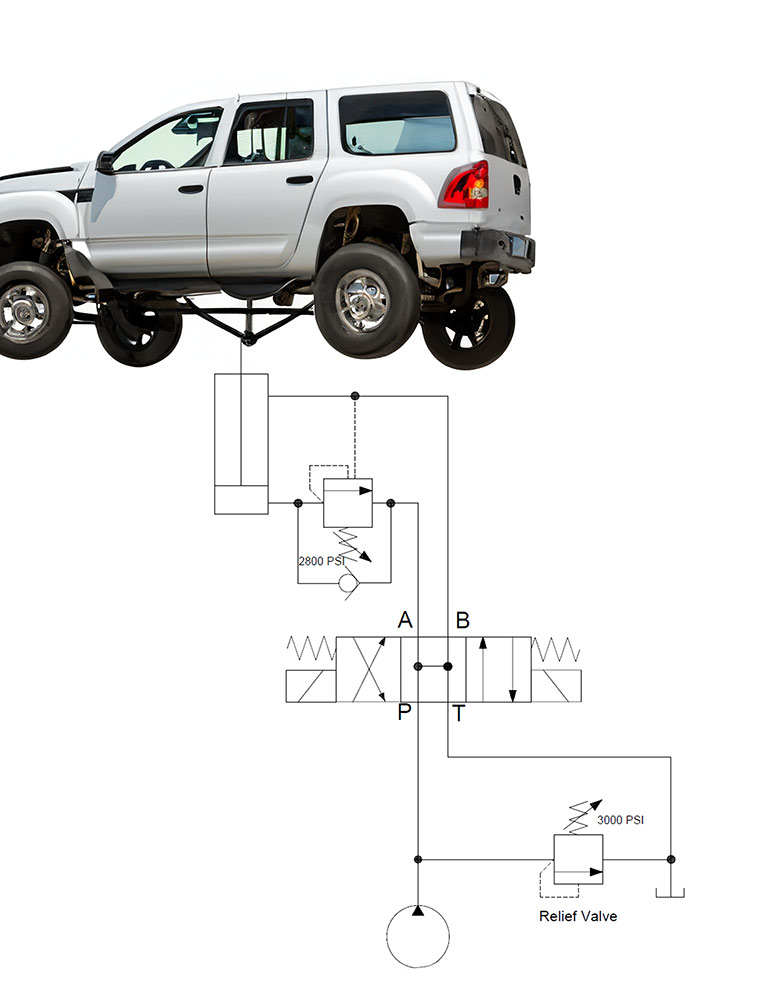
Enter the counterbalance valve — these pressure valves aid in the safe and dynamically balanced lowering of loads at a velocity dictated by the pump flow rate and not mass and gravity. If you have a peek at Figure 1 (note, not a real Ford Raptor and not a real hoist), you can see a sample counterbalance valve circuit.
The circuit is quite simple: just a pump, relief valve, DCV, cylinder and a counterbalance valve. In this case, the counterbalance valve is also capable of holding the load, and before anyone writes to tell me how unsafe it is to use a counterbalance valve for load holding, remember that hoists have safety locking pins.
What’s important to notice in this circuit is the pilot line extending from the rod side port down to the counterbalance valve. Without this pilot signal, the counterbalance valve requires 2,800 psi of load-induced pressure to open and allow the lowering of the (not a) Raptor. We must first send pump fluid to the rod side port to push the hoist down, and with the restricted counterbalance valve blocking the easy exit, back pressure rises from the CB valve inlet port all the way to the pump.
However, we still don’t need 2,800 psi to open up the counterbalance valve. The pilot piston in the CB valve has a larger surface area than the direct-acting portion of the valve so a fraction of the pressure is required to lower the load. The ratio could range from 2:1 to 10:1, although 3:1 provides a great middle ground.
When you have a low pilot ratio, such as 2:1, the valve responds quicky and precisely but can consume a lot more energy. Essentially the valve and cylinder are in what I call hydraulic tension where energy is ready to act quickly. With a 10:1 pilot ratio, the valve opens easily, but the system is less responsive with poorer control. However, the valve opens easily, and wastes very little energy to heat.
You may question what happens when the valve opens from pilot pressure — wouldn’t the load just run away then? The answer is no because once the load starts to run away faster than is being asked by pump flow, the rod side pressure drops below pilot pressure, thereby closing the valve again. Counterbalance valves are not digital — they open at a point of equilibrium and simply help lower the load smoothly and at the pace requested by pump flow.
There are many other applications aside from this simple hoist example where counterbalance valves may be used. Another example is when a pivoting cylinder moves over center to where the load transfers from compression to tension. In this case, you’d place the counterbalance valve on the rod side port.
I’m not exaggerating when I say the counterbalance valve is one of the best hydraulic inventions created, and there are many. They’re an inexpensive and reliable method of controlling loads safely in many applications spanning from industrial to mobile.
Filed Under: Components Oil Coolers, Engineering Basics, Mobile Hydraulic Tips, Technologies, Valves & Manifolds