
Hydraulic hose uses a reinforcement material sandwiched between its inner tube and outer cover. Although modern designs have used anything from textile fiber to polyester, most hydraulic hoses use steel wire as their reinforcement. Within the steel reinforcement type, there are two major construction styles – braided or spiral wire.
 Wire has almost no bending or compression strength, so it’s a given that it offers the hose only tensile strength. But hoses clearly bend, so how does the wire reinforcement add strength to the hose? As pressure attempts to push the tube outward, it also pushes up on the wire. Because the wire is fixed at either end of the hose, it cannot move axially across the hose. The only possible direction of movement, such as the direction of a bubble, causes tension on the wire, which the wire very successfully resists.
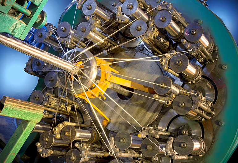
Braided wire hoses are constructed with special machinery engineered to perform a maypole dance around the inner tube, where the wires criss-cross in patches to add strength to the hose. Many wires perform this dance, which results in the braiding looking much like a cylindrical checkerboard. In addition, because each layer of braided wire lays helically around the tube in opposite directions, the wires can slide over and under each other to add flexibility.
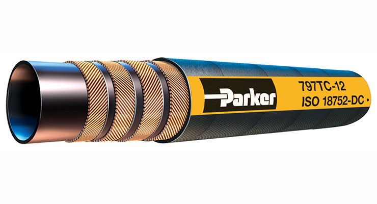
Spiral wound reinforcement is slightly more straightforward to manufacture, operating more like a lathe, with many spools of wiring spinning around the tube as mandrels draw it through the machine. The spiral winding must be tight to prevent gaps in tension force, and all hoses use multiples of two-wire layers. A single layer of wire offers poor torsional strength, but two layers stacked atop the tube in an opposing direction ensure the forces against the wire are equally distributed. You’ll notice spiral hose comes in two, four and six layers of wire.
Because spiral wire experiences less play inside the finished hose, the final product is quite stiff. The spiral construction combined with the high tensile strength offers superior pressure capacity but is detrimental to flexibility. As you would suspect, the stiffness and the pressure holding capacity increase with the four and six layers of wire.
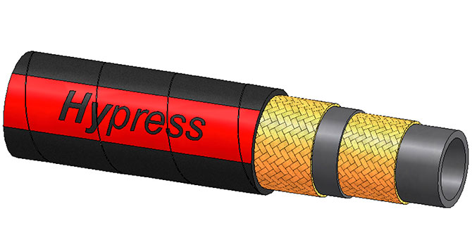
So is the braided hose better, or is the spiral wound hose better? I’m sorry to disappoint you — it depends. Each hose construction type suits a different application. If your application requires high flexibility within reasonable pressure limits – say 3,000 psi or less – a braided hose makes a great choice. The very common 100R1 and 100R2 hoses offer this construction and suits the majority of your standard applications.
If you require ultimate pressure holding capacity, then choose a spiral wire construction for your hose. For example, 100R15 spiral wound hose offers more than 6,000 psi capacity, and it matters not if your required size is 3/8 in. or even 1-1/2 in. However, it happens to be one of the least flexible hose designs.
All things said it’s a great time to be a hose consumer. Manufacturers seem to care less about traditional limitations to hose construction and now offer performance well beyond the norm. You no longer have to limit yourself to low-pressure braided designs because manufacturers offer high-pressure designs offering superior flexibility. If you simply prefer spiral hose, rest well knowing the major players offer high flexibility options while maintaining their ultra-high pressure capacity. No longer do you need to settle on a large diameter spiral hose that handles like a steel tube.
Filed Under: Hose & Tubing, Hose Assembly Tips