
By Linda Caron
Global Product Manager, Factory Automation
Pneumatic Div.
Parker Hannifin Corp.
As more companies increase their focus on machine safety, design engineers need a firm understanding of the Machinery Directive and how to comply with required safety levels. Installing a pneumatic safety exhaust valve can be a simple and cost-effective way to accomplish this aim.
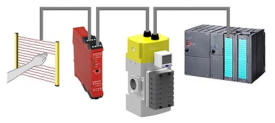
High-level safety circuits must include redundancy and monitoring.
Understanding safety standards
The goal of the Machinery Directive 2006/42/EC is to protect people and the environment from accidents caused by all types of machinery. The EN 954-1 standard, previously used to support the directive, has now been superseded by EN ISO 13849-1 and -2 and EN 62061 standards. A significant revision with these standards is the approach taken to assess safety-related controls systems, especially with regard to modern electronic control circuits.
In essence, the new standard builds on existing categories of safety within EN 954-1 (B, 1, 2, 3, 4) and also adds a new procedure for risk assessment. Instead of categories this new standard of control, called a Performance Level (PL), is associated with a given safety function on a machine. Definitions for diagnostic coverage (DC) and common cause failures (CCF) are also incorporated into this calculation, as is component life (B10d). This ensures that safety is not just focused on component reliability, but also introduces common-sense safety principles such as redundancy, diversity, and fail-to-safe behavior.
Machinery Directive impacts pneumatics
Because pneumatics is part of the Safety Related Parts of the Control System (SRP/CS), machine builders and end users should consider adding a safety exhaust valve into an air-preparation system. A safety exhaust valve lets the user safely and reliably shut off the pneumatic energy, stopping compressed-air flow to the machine and allowing downstream pressure to exhaust. For example, the safety function can activate when operators reach into hazardous areas or during an e-stop condition, as well as to meet the required performance level (PLr) determined by a risk assessment.
Some of the most important considerations when selecting a safety exhaust valve include:
• Easy integration with electronic controls.
• Fast response time to exhaust.
• Minimal residual pressure when faulted.
• Long component life (B10d).
• Small footprint.
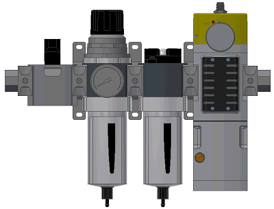
Parker’s modular P33 safety valve combines with filtration and pressure-regulation components, and a soft-start option.
A prime example of a safety exhaust valve that meets these requirements is Parker’s new P33 valve. It is designed for external monitoring, incorporates series-parallel technology for high flows and fast exhausting response with minimal residual pressure in the fault condition, and has a long life with a B10d of 20,000,000 cycles.
It provides straightforward wiring options for most brands of controls, whether used with a safety relay, programmable safety relay or high-end safety PLC. LEDs indicate faults and diagnostics. The P33 valve is modular with Parker 0.75-in. air-entry filtration and pressure-regulation components, and an optional soft-start function does not increase the width of the product.
Series-parallel design
The faster a machine can stop, the closer builders and users can install guards, light curtains and other presence-sensing devices. Valve “stickiness” is one of the biggest variable factors in stopping time, as related to the valve’s exhaust flow capability. Parker uses a patented series-parallel flow design that incorporates the best of both series and parallel arrangements to maximize safety.

The P33 valve has a series-parallel flow design to maximize safety.
Essentially, the two valve elements are arranged such that air from inlet to outlet must pass through both valves in series (as illustrated in red in the graphic), but the flow path from outlet to exhaust is in parallel (shown in orange). Cross-flow technology ensures that both valve elements (redundant design) must shift to supply air downstream and, if either valve element is out of position with the other, downstream air will dump to exhaust in parallel. This arrangement permits higher exhaust flow capability and ensures low residual pressure during a fault, eliminating the danger of residual energy making its way into the machine.
External monitoring
To achieve the highest level of diagnostic coverage, one must employ the best aspects of safety circuit architecture—redundancy (dual-channel circuits) and monitoring. Monitoring detects faults or failures in control systems, and checks for short-circuit faults. The monitoring portion of a safety system must check if both sides of the valve shift together every time—by monitoring the condition of pressure-operated sensors in the P33 valve. These sensors are hardwired into the controls and “monitored” by the external control system.
This is generally done with most safety relays and safety PLCs that can also perform pulse-test monitoring. These types of safety relays and safety PLCs make for reliable systems with high diagnostic coverage—especially, short-circuit faults in dual-channel systems. The use of sophisticated controls and monitoring ensures sensors are not bypassed and the valve functions as intended. Because the P33 is a mechanical fail-safe device, monitoring could also be done via a standard PLC and still attain a rating as high as PL d.
A reset function is usually required to recover from a fault in the safety system. When a valve fault is detected (one pressure sensor not in the correct state), experts recommend incorporating a reset function. This prevents further operation, which could otherwise lead to a build-up of faults and a loss of the safety function. Detection of any fault, though, must shut off the actuating signals to the valve, and they must remain off until a reset is performed. A risk assessment and available machine-specific safety standards should determine whether a dedicated, separate valve reset or an automatic valve reset is appropriate for the specific application.
Component life
One characteristic of any safety component is statistical component life—B10d. When designing a safety system according to ISO 13849-1, each component in the system needs a B10d or a mean time to dangerous failure (MTTFd). Engineers use a B10d value, along with the number of operations (nop) to determine the MTTFd of the component for the application: MTTFd = B10d/nop.
Valves that use electromechanical components for monitoring are usually limited by the life of the monitoring components. Using solid-state electronic pressure sensors for monitoring greatly improves the B10d numbers as there are no mechanical wear components. Therefore, the P33 safety exhaust valve is given as 20,000,000 cycles for B10d.
Evaluating Performance Level
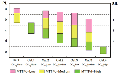
Mean time to dangerous failure (MTTFd) helps determine the system Performance Level, which is similar to the Safety Integrity Level.
The required Performance Level (PLr) should be determined by a risk assessment. Once a PLr is determined, application statistical component life (MTTFd), circuit architecture (Category), monitoring (DC), and consideration of common-cause failures (CCF) can be used to determine the system PL. The system PL must equal or exceed the required Performance Level. This is similar to working with Safety Integrity Levels (SIL). (See the accompanying MTTFd chart for more details.)
For applications where the severity of injury and level of exposure are high, the percentage of diagnostic coverage of the monitoring system must be high as well. Depending on the safety relays or safety PLCs used to control command and monitoring, the system can achieve a high Performance Level, up to PL e and Safe Integrity Level to SIL 3.
If risk assessment demands a safety rating of PL c or higher for the pneumatic system, a dual-redundant safety exhaust valve is a simple-to-implement and cost-effective way to attain the required safety level. Parker’s P33 safe exhaust valve has been designed to fit well into both mid- and high-level safety circuits to ensure machines are properly protected.
Parker Hannifin
www.parker.com/pneumatics
Filed Under: News, Pneumatic Tips, Valves & Manifolds