
Hydraulic reservoirs in a fluid power system primarily serve as a storage tanks to contain sufficient volume of hydraulic fluid and subsequently cater to the fluid demand by the pump during system operation. Additionally, the reservoirs account for the thermal expansion/contraction of the hydraulic fluid and also provide for acceptable levels of external leakage at the dynamic seals.
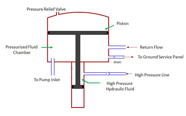
Illustration of the construction of a bootstrap hydraulic reservoir
On a broad scale, the reservoirs are classified into two categories namely, vented to atmosphere type and not vented to atmosphere type. The reservoirs that are vented to atmosphere cannot provide a positive suction pressure at the pump inlet. This will lead to cavitation problems in the pump. However, in not vented type of reservoirs, a positive suction pressure at the pump inlet is always maintained. This is accomplished by pressurizing the fluid in the reservoir either through spring loading, compressed air or use of high -ressure fluid from the system itself. The chamber that contains the pressurized fluid is called the bootstrap chamber and thus this reservoir is commonly referred to as a bootstrap reservoir. Bootstrap reservoirs are commonly used in most of civilian aircraft hydraulic systems. While Airbus A320 family and Boeing B737 use bleed air (from engine) pressurized reservoirs, Airbus A350 and Boeing B787 use hydraulic type reservoirs.
Reservoir capacity is one of the foremost things to be defined by the designer. As a rule of thumb, the reservoir capacity should be three times the output rating of a fixed displacement pump operating in the system. That is, if pump rating is 6 lpm, then the reservoir capacity is 18 L. However, in case of mobile hydraulics and in particular aircraft hydraulic systems, this thumb rule doesn’t hold. Aircraft hydraulic systems operate variable delivery pumps, so the pump output is continuously regulated depending on the requirement. This avoids unnecessary pumping of the fluid. Because demand is reduced, a designer can opt for a smaller sized reservoir that will eventually result in optimization of critical parameters like weight and space. In practice, aircraft hydraulic system reservoirs are sized for only 10% capacity of the pump output rating. In addition, few actuators and accumulators may have large volume capacity. Thus one must consider their respective differential volume.
Further, a well-designed reservoir accommodates thermal expansion/contraction of the fluid due to rise/fall in fluid operating temperature. For a known value of thermal expansion co-efficient of the fluid (Lt/Lt/Deg.C) and known value of net increase in operating temperature (from thermal analysis), the thermal expansion space can be exactly quantified. As a rule of thumb, about 10% of the reservoir capacity is reserved for thermal expansion. It has to be noted here that the presence of an external heat exchanger can greatly reduce the size of reservoir. If an external heat exchanger is not in place, reservoir surface with protruded fins is recommended.
Finally, care should be taken to ensure that the fluid entering the reservoir will not immediately re-enter into the pump inlet port. Sufficient time has to be allotted for the re-entry of such solid contaminants that would settle down and for the fluid to be deaerated. Allowing the aerated fluid into the pump inlet may again result in pump cavitation, defeating the whole purpose of opting for a bootstrap reservoir. To avoid this scenario, baffles are placed within the reservoir to slow down the fluid. All these considerations along with features like on-ground maintenance ports, drain ports, pressure relief valves etc., should suffice the preliminary sizing of a reservoir.
Contributed by Harshavardhan Joshi, Aircraft Hydraulic Systems Engineer, CSIR – National Aerospace Laboratories, India.
The post How do you size hydraulic reservoirs for aircraft hydraulic systems? appeared first on Sealing & Contamination Control Tips.
Filed Under: Fluid Power Basics, Mobile Hydraulic Tips