Fluid Power World

  • Home
  • Technologies
    • Hydraulics
      • Cylinders & Actuators
      • Filtration/Contamination Control
      • Fittings, Couplings & Adapters
      • Fluids
      • Fluid Conditioning
      • Hose & Tubing
      • Pumps & Motors
      • Related Technologies
      • Sealing
      • Sensors & Gauges
      • Valves & Manifolds
    • Pneumatics
      • Air Preparation & Regulation
      • Compressed Air Technologies
      • Cylinders & Actuators
      • End Effectors & Grippers
      • Fittings, Couplings & Adapters
      • Hose & Tubing
      • Sensors
      • Vacuum
      • Valves & Manifolds
  • Engineering Basics
  • Trending
  • Resources
    • Digital Issues
    • Pneumatics Tech Toolbox
    • Podcasts
    • Subscribe to Fluid Power World Print Magazine
    • Videos
    • Webinars / Digital Events
    • White Papers
  • Women in Engineering
    • Women in Fluid Power
    • Women in Engineering
  • Design Guide Library
  • Classrooms
    • Pneumatics Classroom
  • SUBSCRIBE

Compressed air fail: Flowmeter position

By Paul Heney | July 13, 2022

Share
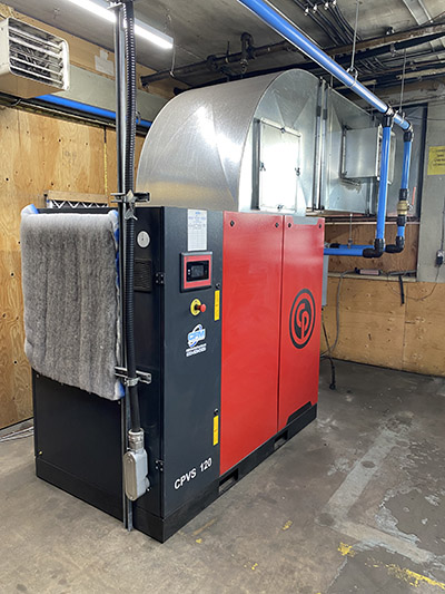
Fig. 1. It is possible to incorrectly size a new compressor if the flow meter readings are not interpreted properly.  This compressor turned out to be too small because the  purge flow readings was not part of the flow meter measurement.

A local food company was resizing its compressed air system while renewing its plant operations. To get the sizing correct, the plant maintenance foreman purchased a flow meter to measure the output of the compressors.

The meter was installed with a data logger to capture the flow profile of the plant. The readings showed that the peak flows were 450 cfm, and the average was 300 cfm — so a main compressor sized at 90 kW was purchased and installed.

Shortly after installation, the maintenance foreman was surprised to see low pressure was occurring, indicating the compressor was too small. The compressor was rated at 500 cfm, yet the flow meter still showed peaks of no more than 450 cfm during the highest production times.

A compressed air auditor was called in to investigate and immediately recognized a problem. The plant was using a heatless desiccant dryer to dry the air — and it was consuming purge flow. The flow meter, being of thermal mass design, was installed after the dryer, so did not capture  the 150 cfm of purge in either the peak or average reading.

The auditor examined the flow meter records and found that the system flow during non-production times was a steady 150 cfm, indicating a high level of leakage. He also tested the air dryer and found the purge flow was 60 cfm higher than normal. With some adjustments and leakage repair, the peak plant loading was reduced enough to ride out plant peaks with the new compressor.

Things are not always what they seem when using thermal mass flow meters. It is important to ensure you have a good grasp of the flow requirements upstream of the meter before sizing compressors.


Filed Under: Air Preparation & Regulation, Pneumatic Tips


About The Author

Paul Heney

Current Digital Issue

  Easier access to more of our content Every other month, readers of Fluid Power World have access to our beautiful print and digital editions, where we share a selection of the best fundamentals content, technology news, case studies, and technical articles that cover the gamut of hydraulics and pneumatics system design. But we only…

Subscribe!

Fluid Power World is written by engineers for engineers engaged in designing machines and or equipment in Off-Highway, Oil & Gas, Mining, Packaging, Industrial Applications, Agriculture, Construction, Forestry, Medical and Material Handling. Fluid Power World covers pneumatics, mobile hydraulics and industrial hydraulics.

Fluid Power Design Guides

fluid
“fpw
EXPAND YOUR KNOWLEDGE AND STAY CONNECTED
Get the latest info on technologies, tools and strategies for Fluid Power Professionals.

RSS Featured White Papers

  • Moving fluid power forward
  • High-force linear motion: How to convert from hydraulic cylinders to electric actuators and why.
  • A technical comparison: Performance of pneumatic cylinders and electric rod actuators
Fluid Power World
  • Hose Assembly Tips
  • Mobile Hydraulic Tips
  • Pneumatic Tips
  • Sealing & Contamination Control Tips
  • About us
  • Contact Us

Copyright © 2024 WTWH Media LLC. All Rights Reserved. The material on this site may not be reproduced, distributed, transmitted, cached or otherwise used, except with the prior written permission of WTWH Media
Privacy Policy | Advertising | About Us

Search Fluid Power World

  • Home
  • Technologies
    • Hydraulics
      • Cylinders & Actuators
      • Filtration/Contamination Control
      • Fittings, Couplings & Adapters
      • Fluids
      • Fluid Conditioning
      • Hose & Tubing
      • Pumps & Motors
      • Related Technologies
      • Sealing
      • Sensors & Gauges
      • Valves & Manifolds
    • Pneumatics
      • Air Preparation & Regulation
      • Compressed Air Technologies
      • Cylinders & Actuators
      • End Effectors & Grippers
      • Fittings, Couplings & Adapters
      • Hose & Tubing
      • Sensors
      • Vacuum
      • Valves & Manifolds
  • Engineering Basics
  • Trending
  • Resources
    • Digital Issues
    • Pneumatics Tech Toolbox
    • Podcasts
    • Subscribe to Fluid Power World Print Magazine
    • Videos
    • Webinars / Digital Events
    • White Papers
  • Women in Engineering
    • Women in Fluid Power
    • Women in Engineering
  • Design Guide Library
  • Classrooms
    • Pneumatics Classroom
  • SUBSCRIBE