
By Josh Cosford, Contributing Editor
Sensors used in fluid power are available to measure anything from pressure, flow, temperature, position and more. Understanding their differences will help you better maintain an efficient system.
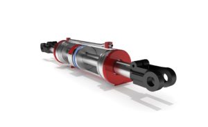
These small linear transducers from Rota Engineering are designed for position control/monitoring of mobile hydraulic cylinders. They withstand both physical abuse and exposure to dust, water, and more.
Sensor is a rather arbitrary word as it relates to the observation or measurement of fluid power characteristics. Anything that can sense pressure, flow, temperature, position, or any other quality of liquid or air, is a sensor. By that definition, both you and I are sensors. I can put my hand on a pump and tell you if it’s hot or cold. I can look at a cylinder and tell you if it’s fully retracted, more or less.
It goes without saying I would do a poor job just standing around with my hand on a pump, or looking at cylinders to observe their position. Not only would my crushed L4-L5 disc be screaming for mercy after an hour of standing around, my actual capacity to measure temperature is terrible at best. If your resolution was no finer than “cold,” “warmish,” and “hot,” then maybe we could talk. Otherwise, there are devices on the market much more accurate, and unless you are looking for something lost or hidden, my descriptions are useless.
To measure something like temperature, you can get actual thermometers to achieve a level of accuracy far beyond any human I know. But besides the odd fact thermometers used in the fluid power industry are called temperature gauges, these gauges are still not what are described as sensors. Let’s just give up on understanding the etymology of the fluid power dictionary, because the confusion doesn’t end there.
Electronic sensors or transducers
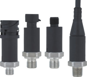
This MH-3 mobile working machines pressure transmitter from WIKA Instrument is designed to limit overpressure failures and diagnose problems on the spot.
Sensors are the electronic devices uses to measure any quality of liquid or air important to the operation of a fluid power machine. How a temperature gauge isn’t a sensor is beyond me, but unless you’re talking about Cosford’s Law, I didn’t make this stuff up, I just write about it. It’s important to note these sensors are electronic, meaning they require a source of power to provide their reading or output, with one exception I’ll mention shortly.
Electronic sensors require a power source so their hardware can detect and measure the quality they’re designed to. Most sensors will require a 12 or 24 Vdc source, or a 120 Vac source (which will be converted to dc internally, anyway). Some sensors will be battery powered, and there are even some that are solar powered. Regardless, most sensors require an input power source because of the nature of their electronic circuits.
Wheatstone bridges, voltage dividers or other electronic circuits are used to convert the input power into a variable signal to be interpreted by another device, such as a display or PLC. I can no more explain the operation of a wheatstone bridge than I can a PLC, because I’m a hydraulics guy, but perhaps one of the editors over at Sensor Tips or Analog IC Tips can provide more clarity. Regardless, this article is about hydraulic and pneumatic sensors and their applications, rather than electronics.
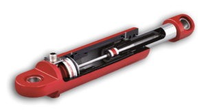
Linear transducers, such as this MH/R series for mobile/industrial applications from MTS Sensors, accurately sense piston and stroke positions. A magnet is permanently attached to the piston, and a probe is inserted inside the hollow piston/rod assembly.
What I can tell you is that sensors are available in various output signals, either analog or digital. Sensors in the fluid power industry are most often called transducers, which is any device that converts a mechanical property into an analog electrical signal. The electrical output signal of an analog transducer is usually either a variable output of voltage or amperage. The transducer will use its input power, and using a wheatstone bridge or other technique, converts the mechanical input into the variable electrical output.
How do they work?
The most common outputs used in fluid power are 0-5 or 0-10 V, and 0-20 or 4-20 mA. The choice of output is partially preference to the designer, and also partially related to application. For example, a variable voltage output is more desirable to most PLC’s, but can be prone to electromagnetic interference from other machinery, especially over a long distance of cable. The interference can change the voltage of the signal, creating noise or inaccuracy.
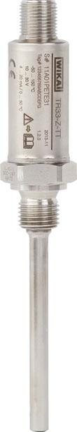
Temperature sensors, like WIKA’s TR33 miniature resistance thermometer, are rated to pressures of 140 bar and temperatures to 250° C.
However, a variable resistance output such as 4-20 mA is more stable, as it doesn’t rely on voltage. Any interference that influences voltage in the cable running from the transducer to the PLC will not affect the amperage. The downside, of course, is most controllers prefer a variable voltage input. Sometimes an analog transducer will simply plug into a digital display, providing visual indication of the amplitude of the quality you’re measuring.
Regardless, if you’re using a PLC, display or other device with your transducer, you will often have to program your measuring range into the controller. For example, a pressure transducer is designed to measure gauge pressure accurately over specified range. The measuring range could be 0 to 100 psi or anywhere up to 10,000 psi or more. Your controller has no idea what the measurement range is, so the parameters must be entered to define this measurement range.
If you have a 0-10 V transducer with a measuring range of 5000 psi, you must tell the controller that 10 V equals 5000 psi. This way, it will know that 5 V output from the transducer is equal to 2500 psi of hydraulic pressure, or any range in between. You may also have a 4-20mA transducer measuring up to 100 psi. In this case, 4 mA of resistance is set at the zero pressure point, and the controller is programmed to recognize 20 mA as 100 psi. Anything up to the 4mA dead band is simply read as zero pressure.
It should be noted that should pressure rise above the measurement range, it will not be recognized by the controller. If you have a 0-10 V transducer with a 1,000-psi measurement range, and pressure jumps to 1200 psi, your controller will be oblivious, for the most part. The transducer will not put out much more than 10 V, so the controller will read 1,000 psi. Some transducers are designed with a max overload pressure where it will not damage the device, which can be double the measurement range for reliability. However, burst pressure could be ten times the measurement range, so it’s important to consider what pressure range you actually need to accurately measure.
So why not use a 10,000 psi transducer for your 1,500 psi system, so it’s nearly impossible to blow your sensor apart? It’s because choosing a measurement range pertinent to your application ensures you have the highest level of resolution and accuracy. With only 0-10 V available as resolution, your transducer would have a usable output range of only 0-1.5 V. The accuracy within 1.5 V is inferior to using the whole 10 V available, where 10 V equals 1,500 psi if you chose the correct sensor to begin with. Truthfully, you would want to choose a transducer slightly higher than your measurement range, say 2,000 psi in this case, just in case of over-pressure situations you want to observe.
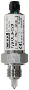
WIKA’s OLS-C20 level sensor is an optoelectronic level switch designed for high pressures.
A digital transducer differs from analog transducer types because they typically send out a signal conforming to one of the various network CAN bus protocols, such as CANopen, DeviceNet et al. The digital can signal can allow nearly limitless devices (or nodes) in the network while using only four wires to connect it all. If your sensor is a node in the CAN network, it has a built in controller that internally converts its own analog range into a digital signal fed over the network.
There are many advantages to a digital network, although their cost is higher than a standard, non-network controller setup. One is the lack of excessive wiring, as already mentioned, but another is the length of distance possible between sensor and controller. For example, your temperature transducer could be set to measure a 0-200°F range, and using fiber-optic cables, can send its signal miles away to a PLC in the network.
The non-electronic exception to the sensor rule is the use of variable resistors. They can be thermistors, for example, which change their resistance based on temperature. Any controller able to measure changes in resistance can interpret the signal and relay temperature through a display digital signal. Cylinder positioning can also be observed using a variable resistor, although this technology is old hat with the popularity of linear transducers used in cylinder applications. The variable resistor is simply a device spanning the length of measurement, with a brush that moves the length of the resistor. The farther the brush moves away from the base point, the higher the resistance, and this resistance can be interpreted by the PLC just as with the thermistor. The advantage if resistors is they require only an in and out connection, and no power source.
Multiple styles for most measurements
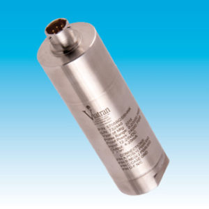
Pressure transmitters often need to be rated for hazardous and harsh environments, such as this model 570 pressure transmitter from Viatran.
Sensors are available for every conceivable quality you could wish to measure. Temperature transducers are available to measure up to over 200°F for fluid power systems. Ranges higher than that are available for other markets, but unnecessary for fluid power. If your hydraulic oil is 195°, you have bigger issues than if your transducer is about to run out of measurement range.
Pressure transducers are the most common electronic sensor used in fluid power. They can provide upwards of 0.10% accuracy over their full range, and response time within 0.5 milliseconds. Should you be having issues related to pressure spikes, you can log the pressure data on your machine to see when and where the problem is occurring. Even without data logging, they provide an accurate real-time readout of system pressure, anywhere you wish to mount it and a display.
If you have a high-performance motion control application, the chances are good you have a linear position sensor on your hydraulic cylinder. These are sometimes called LVDTs or LVTs [Linear Variable (Differential) Transformers], but these linear transducers can accurately sense piston and stroke positions. A magnet is permanently attached to the piston, and a probe is inserted inside the hollow piston/rod assembly. They can be a simple hall effect or advanced design like MTS’s Temposonic, which is highly accurate. As the cylinder strokes, the magnetic field is picked up by the transducer, relaying the signal back to the PLC.
For industrial applications, the hardware, which includes the onboard electronics, will often protrude from the cap end of the cylinder. This configuration makes clevis mount cylinders difficult, so switching to a rear trunnion would be a better option. Electronic output can vary vastly, and can literally be any signal usable by today’s controllers; variable amperage, variable voltage, PWM or even any of the many CAN protocols. Mobile applications aren’t so free with cap end space, and are nearly always clevis or swivel rod eye mounts, so the linear transducers are compact enough to be integrally mounted in the cylinder, although they are often less sophisticated.
Other measurement possibilities are water saturation level, flow rate, actuator position and velocity, viscosity and contamination level, to name a few. There are so many accurate tools available to monitor the condition of your fluid, there really is no excuse for machine failure and downtime. If you can measure temperature and viscosity, as well as water and particle contamination levels, you can predict 99% of hydraulic failures before they happen, and your PLC can even shut a machine down should any of these sensors read past a critical level.
Just as with consumer electronics, sensors used in the fluid power industry are plummeting in cost, and are quite economical. There really is no good reason not to hop on board and take advantage of both electronic measurement and electronic control of your fluid power system. Although the fluid power industry has always been a late adaptor to electronics, the choice of sensors available at low cost make it a no-brainer to jump on board now.
Filed Under: Fluid Power World Magazine Articles, Mobile Hydraulic Tips, Sensors