Fluid Power World

  • Home
  • Technologies
    • Hydraulics
      • Cylinders & Actuators
      • Filtration/Contamination Control
      • Fittings, Couplings & Adapters
      • Fluids
      • Fluid Conditioning
      • Hose & Tubing
      • Pumps & Motors
      • Related Technologies
      • Sealing
      • Sensors & Gauges
      • Valves & Manifolds
    • Pneumatics
      • Air Preparation & Regulation
      • Compressed Air Technologies
      • Cylinders & Actuators
      • End Effectors & Grippers
      • Fittings, Couplings & Adapters
      • Hose & Tubing
      • Sensors
      • Vacuum
      • Valves & Manifolds
  • Engineering Basics
  • Trending
  • Resources
    • Digital Issues
    • Pneumatics Tech Toolbox
    • Podcasts
    • Subscribe to Fluid Power World Print Magazine
    • Videos
    • Webinars / Digital Events
    • White Papers
  • Women in Engineering
    • Women in Fluid Power
    • Women in Engineering
  • Design Guide Library
  • Classrooms
    • Pneumatics Classroom
  • SUBSCRIBE

Compressed air fail: Pressure increase

By Paul Heney | November 5, 2024

Share

Normally when measuring the pressure gradient of a compressed air system in an industrial site, the pressure at the compressor discharge is the highest of all locations. Once the compressed air travels through piping, filters, air dryers, and other components — each causing restriction to flow — the pressure at the far end of the plant will be lower.

But this is not always the case! In a handful of compressed air audits, the air pressure at the far end of the piping was found to be higher than at the compressor discharge. This effect happens when the end of the line is very deep in a mine. Fig. 1 shows this effect.

Fig. 1. In this mine, the gauge pressure at the discharge of the compressor (blue line) is lower that at 5,400- and 6,300-foot levels underground.

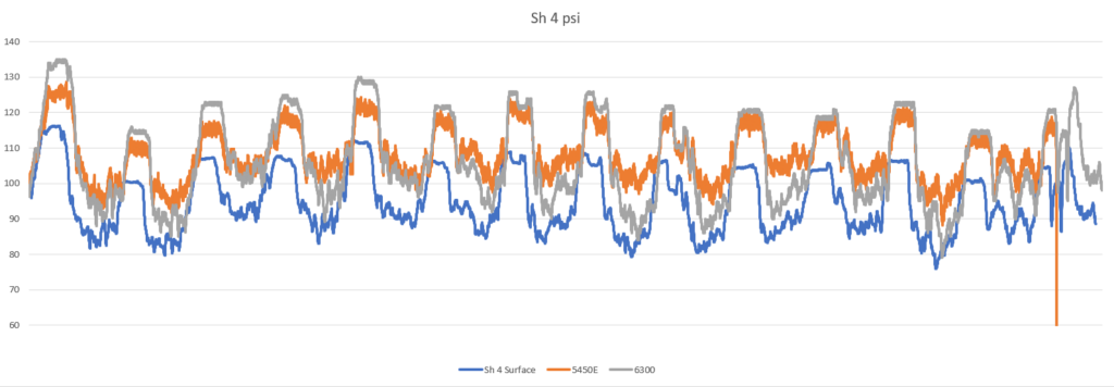
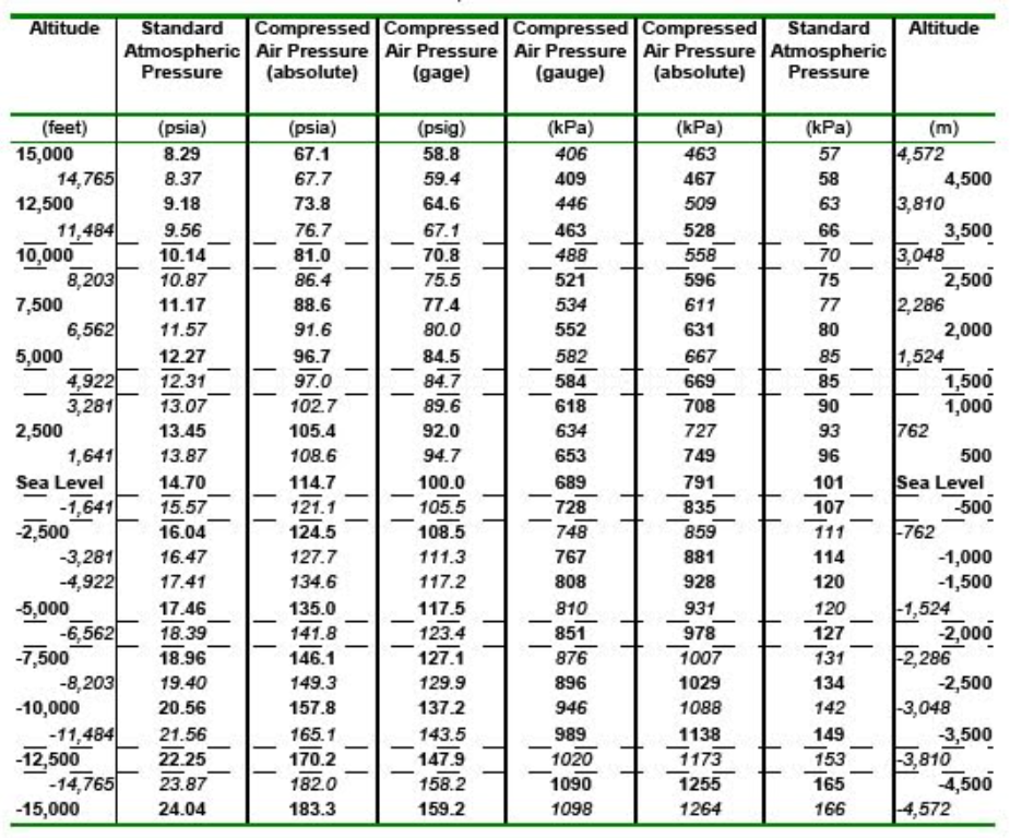
The compression effect is similar to the pressures that develop in the bottom of a swimming pool, where the weight of the column of water creates higher pressure. In a mine, the weight of the column of air in the shaft piping creates about 10 psi of extra pressure for every 3,000 feet in depth. The effect and the mathematics behind it can be viewed at this link.

This self-compression effect needs to be considered when designing equipment in a mine so as not to exceed pressure ratings. The higher pressure causes all unregulated uses, including leakage to consume about 1% more compressed air for every 1 psi in excessive pressure.

Fig. 2. Pressure chart showing compression effect at various altitudes and depths

Another effect of this compression it the retention of water vapor. Air that is on surface at lower pressure can hold more water than air that is compressed at the bottom of the shaft. So if the air is not dried, there will be moisture dropping out in the piping. This water must then be pumped back up to surface for disposal — an expensive operation in a deep mine.


Filed Under: Air Compressors, Air Preparation, Components, Components Oil Coolers, Compressed Air Technologies, Pneumatic Tips, Technologies


About The Author

Paul Heney

Current Digital Issue

  Easier access to more of our content Every other month, readers of Fluid Power World have access to our beautiful print and digital editions, where we share a selection of the best fundamentals content, technology news, case studies, and technical articles that cover the gamut of hydraulics and pneumatics system design. But we only…

Subscribe!

Fluid Power World is written by engineers for engineers engaged in designing machines and or equipment in Off-Highway, Oil & Gas, Mining, Packaging, Industrial Applications, Agriculture, Construction, Forestry, Medical and Material Handling. Fluid Power World covers pneumatics, mobile hydraulics and industrial hydraulics.

Fluid Power Design Guides

fluid
“fpw
EXPAND YOUR KNOWLEDGE AND STAY CONNECTED
Get the latest info on technologies, tools and strategies for Fluid Power Professionals.

RSS Featured White Papers

  • Moving fluid power forward
  • High-force linear motion: How to convert from hydraulic cylinders to electric actuators and why.
  • A technical comparison: Performance of pneumatic cylinders and electric rod actuators
Fluid Power World
  • Hose Assembly Tips
  • Mobile Hydraulic Tips
  • Pneumatic Tips
  • Sealing & Contamination Control Tips
  • About us
  • Contact Us

Copyright © 2024 WTWH Media LLC. All Rights Reserved. The material on this site may not be reproduced, distributed, transmitted, cached or otherwise used, except with the prior written permission of WTWH Media
Privacy Policy | Advertising | About Us

Search Fluid Power World

  • Home
  • Technologies
    • Hydraulics
      • Cylinders & Actuators
      • Filtration/Contamination Control
      • Fittings, Couplings & Adapters
      • Fluids
      • Fluid Conditioning
      • Hose & Tubing
      • Pumps & Motors
      • Related Technologies
      • Sealing
      • Sensors & Gauges
      • Valves & Manifolds
    • Pneumatics
      • Air Preparation & Regulation
      • Compressed Air Technologies
      • Cylinders & Actuators
      • End Effectors & Grippers
      • Fittings, Couplings & Adapters
      • Hose & Tubing
      • Sensors
      • Vacuum
      • Valves & Manifolds
  • Engineering Basics
  • Trending
  • Resources
    • Digital Issues
    • Pneumatics Tech Toolbox
    • Podcasts
    • Subscribe to Fluid Power World Print Magazine
    • Videos
    • Webinars / Digital Events
    • White Papers
  • Women in Engineering
    • Women in Fluid Power
    • Women in Engineering
  • Design Guide Library
  • Classrooms
    • Pneumatics Classroom
  • SUBSCRIBE