
For novices in the fluid power industry, lack of understanding between the fixed flow and variable flow pumping concepts is quite common. A hydraulic pump has one mission, and that is to transform incoming mechanical energy at its shaft into hydraulic energy capable of transferring force to actuators somewhere downstream. This transfer of force is common to both fixed and variable pumps, but the method delivery is quite different.
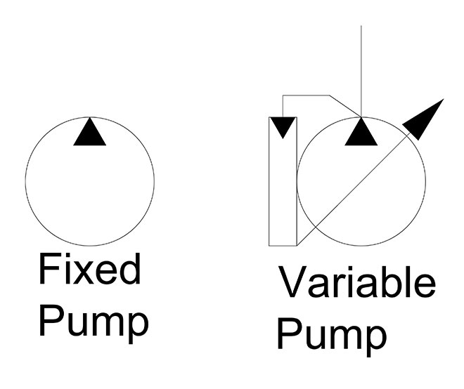
Fixed and variable pumps symbols
The displacement of a pump is defined by the theoretical volume the gears, vanes or pistons will displace in one revolution. If a pump is 30 cc, it will theoretically push 30 ml of fluid in a single rotation, or about 1.8 in.3. With a fixed displacement pump, these 30 cm3 do not change, regardless of how the pump is controlled or what occurs downstream. In reality, actual flow varies based on efficiency, speed and pressure, but that’s a different story. If you need less flow than the pump is rated for, the excess flow must be diverted or relieved to tank.
A variable displacement pump has a method of increasing or reducing displacement either manually, hydraulically or electronically. The method of displacement change depends upon the pump’s structure, differing between piston and vane pumps, and between those two, iterations still.
An axial piston pump’s maximum displacement is determined by the quantity and bore area of the pistons multiplied by the stroke length. Although the stroke length can be fixed, such as with most radial and bent-axis piston motors, the stroke can also be varied. Variable displacement axial piston pumps use a swashplate to guide the pistons as they reciprocate while rotating about the shaft’s axis. The angle the swashplate sits at relative to the pistons dictates how long or short the piston stroke is, and with variable pumps, the swashplate is supported by bearings or bushings.
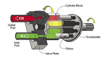
Piston pump
On opposing sides of the swashplate sits a bias piston (and spring) and a control piston. A variable displacement piston pump is designed to be “on stroke,” meaning it wants to pump with full displacement whenever possible. The control piston is operated by what is essentially a relief valve, and if downstream pressure rises above this pressure compensator setting, it will push the control piston out to reduce the angle of the swashplate. With the swashplate angle reduced, the pistons now travel a fraction of their stroke potential. Because displacement is dictated by the area, quantity and stroke of the pistons, pump volume is now reduced. If downstream pressure is still higher than the compensator setting, the stroke will be reduced until the swashplate angle is nearly zero, where it only pumps enough to maintain lubrication.
Swashplate angle can be changed mechanically, with a lever or wheel, but in advanced applications, electro-proportional valves operate the control piston to adjust pump flow as required. This is an advanced concept used in closed loop electronic control applications. A proportional pressure valve will adjust the control piston of the pump with guidance from the PLC, providing exact flow required by the machine under varying conditions.
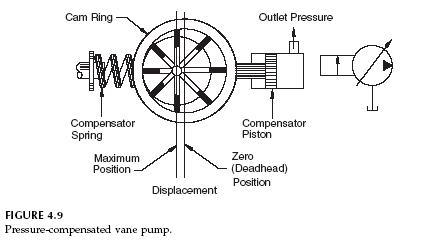 A variable-displacement pressure-compensated vane pump works quite differently from a piston pump. Instead of reciprocating pistons, the rotating group of a vane pump is exposed to suction and pressure chambers inside the housing. The vanes move outward and inward inside the cam ring which is offset compared to the axis of the rotating group. There exists a control piston in a variable vane pump, but this time it pushes against the cam ring. When downstream pressure rises, the control piston pushes the cam ring towards the center of the housing, reducing the difference in alignment between it and the rotating group. This reduces effective displacement, reducing flow to reduce downstream pressure.
Filed Under: Mobile Hydraulic Tips