Fluid Power World

  • Home
  • Technologies
    • Hydraulics
      • Cylinders & Actuators
      • Filtration/Contamination Control
      • Fittings, Couplings & Adapters
      • Fluids
      • Fluid Conditioning
      • Hose & Tubing
      • Pumps & Motors
      • Related Technologies
      • Sealing
      • Sensors & Gauges
      • Valves & Manifolds
    • Pneumatics
      • Air Preparation & Regulation
      • Compressed Air Technologies
      • Cylinders & Actuators
      • End Effectors & Grippers
      • Fittings, Couplings & Adapters
      • Hose & Tubing
      • Sensors
      • Vacuum
      • Valves & Manifolds
  • Engineering Basics
  • Trending
  • Resources
    • Digital Issues
    • Pneumatics Tech Toolbox
    • Podcasts
    • Subscribe to Fluid Power World Print Magazine
    • Videos
    • Webinars / Digital Events
    • White Papers
  • Women in Engineering
    • Women in Fluid Power
    • Women in Engineering
  • Design Guide Library
  • Classrooms
    • Pneumatics Classroom
  • SUBSCRIBE

What is pressure compensation?

By Josh Cosford | December 22, 2016

Share

Prince-Hydraulics-2040-2041-Flow-Control

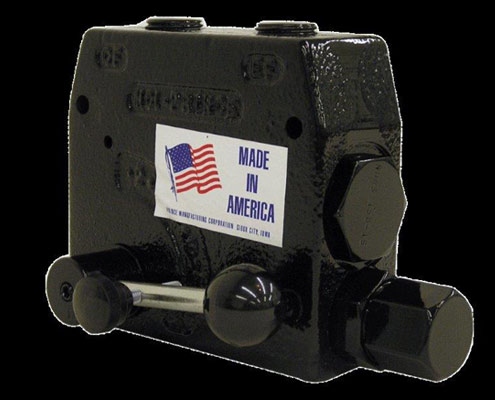
Flow control valves, such as the Prince valve, help with pressure compensation. This valve from Prince Manufacturing is a pressure compensated adjustable flow control valve. By rotating the handle, the flow out the “CF,” or controlled flow port, can be varied from approximately 0 to the maximum controlled flow allowed. Any remaining flow is bypassed to the “EF” or excess flow port. This flow can be used to power another circuit or can be returned to tank. Once the controlled flow is set it will remain nearly constant with variations in pressure on either the controlled or excess flow ports.

You’ve been around hydraulics a while, haven’t you? With that in mind, you probably take some things for granted. There is plenty of jargon in our industry, and it isn’t learned overnight. However, if you were like me, the term pressure compensation was difficult to grasp early in your hydraulic career. If you still don’t quite get it, here’s a quick explanation of pressure compensation.

Fluid flows through components and plumbing at a rate dictated by pressure potential. If you measure pressure at point A close to your pump, and also at point B at your actuator, the difference in those two pressures is the energy available for the fluid to literally get from point A to point B. The higher this difference, the more energy there is for flow to take place. The closer point B pressure is to point A pressure, the less flow potential can take place. In hydrodynamic applications, you lose the ability to achieve velocity in your actuators because of the energy lost to flowing.

With positive displacement systems like hydraulics, which we call hydrostatics, it’s the physical force applied from the pump that pushes the oil like a physical rod. It’s literally force transfer occurring, rather than energy being contained in the inertia of the fluid moving. In this case, if fluid is pumped through one passageway, flow is not affected by pressure differential between point A and point B, except in what is lost to leakage. I should note leakage rates increase as pressure increases, but the same can occur in hydrodynamic applications.

The problem with changes in pressure at point B, is that it changes pressure differential between it and point A. This pressure differential is critical to dictate flow rates, especially when metering of fluid rate is employed. If point A is a constant 3,000 psi, and your orifice is 0.140 in., you will flow about 26 gpm. With no other changes but adding a load from a downstream motor that uses 2,000 psi flow suddenly drops to just over 15 gpm with only 1,000 psi left for flow potential (the difference between point A and point B). The rest of the 11 gpm being created by the pump would then go over the relief valve.

If you change your orifice to a pressure compensated metering valve and set it to flow about 26 gpm at 3,000 psi, it will do exactly that … always. When you run your motor using 2,000 psi of work pressure, you’re still only left with 1,000 psi to move fluid through the metering valve. Only this time, the valve self-pilots open to increase its effective diameter closer to 0.185 in., which is enough to flow 26 gpm at 1,000 psi. The valve compensates for changes in downstream pressure by opening and closing to increase or decrease its orifice.

Essentially, pressure compensation is when a hydraulic component can ready load or system pressure and adjust itself to make up for changes in those pressures. It could be a pressure compensated pump which reduces flow when downstream pressure rises too high, or a pressure compensated flow control which increases flow potential when downstream pressure rises.

Mobile Hydraulic Tips


Filed Under: Mobile Hydraulic Tips, Slider, Valves & Manifolds


About The Author

Josh Cosford

Current Digital Issue

  Easier access to more of our content Every other month, readers of Fluid Power World have access to our beautiful print and digital editions, where we share a selection of the best fundamentals content, technology news, case studies, and technical articles that cover the gamut of hydraulics and pneumatics system design. But we only…

Subscribe!

Fluid Power World is written by engineers for engineers engaged in designing machines and or equipment in Off-Highway, Oil & Gas, Mining, Packaging, Industrial Applications, Agriculture, Construction, Forestry, Medical and Material Handling. Fluid Power World covers pneumatics, mobile hydraulics and industrial hydraulics.

Fluid Power Design Guides

fluid
“fpw
EXPAND YOUR KNOWLEDGE AND STAY CONNECTED
Get the latest info on technologies, tools and strategies for Fluid Power Professionals.

RSS Featured White Papers

  • Moving fluid power forward
  • High-force linear motion: How to convert from hydraulic cylinders to electric actuators and why.
  • A technical comparison: Performance of pneumatic cylinders and electric rod actuators
Fluid Power World
  • Hose Assembly Tips
  • Mobile Hydraulic Tips
  • Pneumatic Tips
  • Sealing & Contamination Control Tips
  • About us
  • Contact Us

Copyright © 2024 WTWH Media LLC. All Rights Reserved. The material on this site may not be reproduced, distributed, transmitted, cached or otherwise used, except with the prior written permission of WTWH Media
Privacy Policy | Advertising | About Us

Search Fluid Power World

  • Home
  • Technologies
    • Hydraulics
      • Cylinders & Actuators
      • Filtration/Contamination Control
      • Fittings, Couplings & Adapters
      • Fluids
      • Fluid Conditioning
      • Hose & Tubing
      • Pumps & Motors
      • Related Technologies
      • Sealing
      • Sensors & Gauges
      • Valves & Manifolds
    • Pneumatics
      • Air Preparation & Regulation
      • Compressed Air Technologies
      • Cylinders & Actuators
      • End Effectors & Grippers
      • Fittings, Couplings & Adapters
      • Hose & Tubing
      • Sensors
      • Vacuum
      • Valves & Manifolds
  • Engineering Basics
  • Trending
  • Resources
    • Digital Issues
    • Pneumatics Tech Toolbox
    • Podcasts
    • Subscribe to Fluid Power World Print Magazine
    • Videos
    • Webinars / Digital Events
    • White Papers
  • Women in Engineering
    • Women in Fluid Power
    • Women in Engineering
  • Design Guide Library
  • Classrooms
    • Pneumatics Classroom
  • SUBSCRIBE