
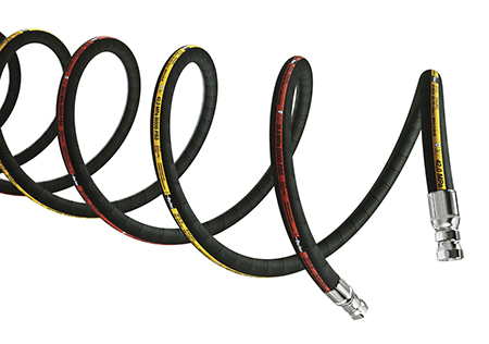
 The minimum bend radius of hydraulic hose represents the smallest diameter that a looped hose can achieve. A hydraulic hose is constructed of three layers, each of which adds to the stiffness of the hose; the tube, the reinforcement(s) and the cover. Depending on the nature of these layers, the bend radius changes.
Although tubes can be constructed of stiff materials, like Teflon, it is typically the reinforcement layers adding the majority of the stiffness to the hose. Reinforcement layers can be one or two layers of braided steel or six or more layers of spiral wound steel. Braided steel is typically more flexible, and has a tighter bend radius than spiral hose.
The number of braids or spirals also affects the minimum bend radius of hydraulic hose. Two layers of braided wire will add more stiffness to the hose than will one layer of wire. As well, four spiral wound wire layers will have more stiffness than just two, and six or eight layers will be that much stiffer with a large bend radius.
 Higher pressure hoses require more layers of reinforcement, and they have the side effect of a large bend radius. The nature of hydraulic hose construction allows smaller diameter hoses to handle pressure more easily, as their internal diameter has less perpendicular surface area for pressure to act against. A small diameter hose can operate at 3000 psi with just one layer of spiral hose, making it naturally flexible. A larger diameter hose may require four layers of spiral wire to handle 3000 psi, making it very stiff with a large bend radius.
Even with the same hose construction type, flexibility is lost as diameter increases. For example, a typical 1/4in. ID 1-wire braided hose (rated for 3200 psi) has a bend radius of 1.5 inches. The same construction hose in 1-in. ID (rated for 1300 psi) has a bend radius of 5.5 inches. If we use a spiral hose example, the same 1/4-in. ID hose (rated for 5100 psi) has a minimum bend radius of 5 inches. Stepping up to 1-in. ID (still rated for 5100 psi), the spiral wound hose has a minimum bend radius of 12 inches.
The post What is the minimum bend radius for hydraulic hose? appeared first on Hose Assembly Tips.
Filed Under: Hose Assembly Tips