
The high-tech engineering company transfluid from Schmallenberg has further developed its t project software. The two versions cover different areas of tube processing. The connection to CAD, BDE (Manufacturing Execution System) or ERP systems, to bending machines or bending robots makes the software flexible for each task. This way it is possible to test different bending techniques in advance and be sure that there are no collisions. The various add-on modules contain the data for complete processes, to have better control over the process and to manage the forming techniques. t project also helps with cutting and minimizing scrap.
The idea of the transfluid t project software is to approach controlled manufacturing systematically. It makes the complex simpler and helps to guarantee the compatibility with the most common interfaces, like IGES, STEP or JT.
transfluid has developed two versions of the software, so it can be used in different applications of tube processing and for custom solutions: t project Basic and t project Professional. Each can be used to meet the requirements of specific tasks.
Tube geometries that are produced or changed with t project can now be saved in an IGES format. This makes it possible to transfer these tube geometries back into a CAD system, after a necessary change or prototype development. An adjustment can be necessary if the collision test shows that it is not possible to bend the tube as planned on the bending machine or for those geometries which are not created in a CAD but prototyped directly on the machine.
A strong feature of the software is it reduces the necessary number of steps necessary to manufacture a finished component and this makes the production more efficient. The software eliminates any possible collisions with the equipment, the tools and the environment before the actual bending process with the machine starts. It tests the feasibility of the tube geometry. The necessary tool and machine parameters are imported online from the t project software in connection with the CAD system.
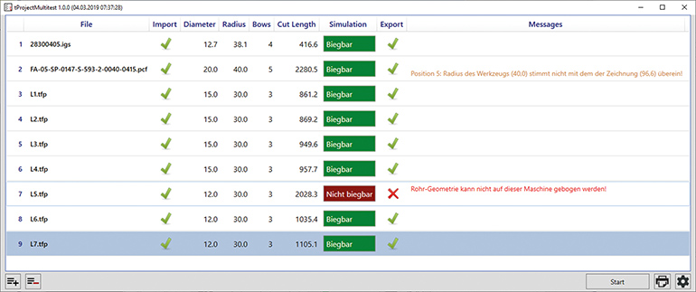
When it is necessary to test a large quantity of bending geometries it is possible to make a list with the tubes to test and their feasibility will be checked automatic sequentially. The data for the tube is automatically imported from the CAD system, any necessary adjustments are automatic calculated and a collision test is performed. This happens automatically. When all the tubes on the list have been tested a decision can be made on the basis of simulation results. For each tube that cannot be bent it can be decided to run a real-life test and make any adjustments manually.
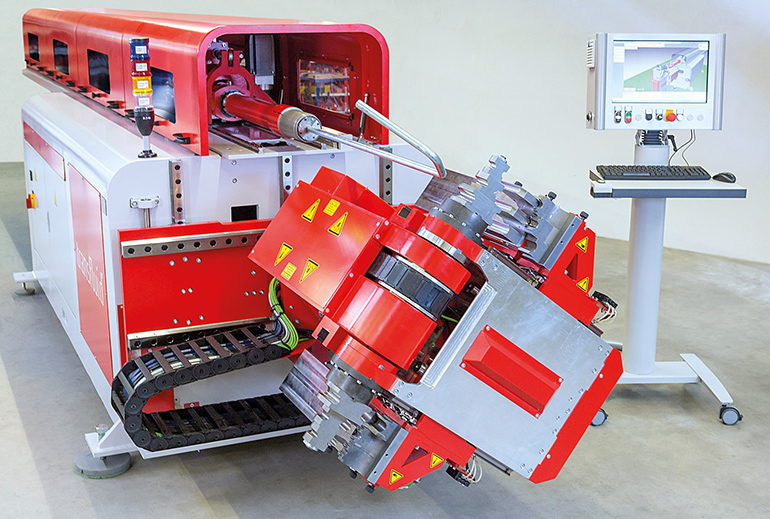
When a bending robot is used the software can process the data without the need to program the robot manually. The data can be loaded and modified just as easy as with a standard bending machine. Pre-installed software generates all the necessary movement sequences of the robots. The automated, product-specific adjustment of the bending speed, which all transfluid machines have, makes it possible to process long tubes without oscillations and safely.
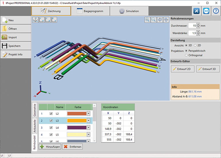
Another innovation of the transfluid software is the expanded display of the drawing editors. For instance, you can display other tubes next to the tube being designed. That is particularly interesting with hydraulic tubing, when tubes have to be dropped side by side or in bundles. In this case one tube is the master tube and all the other tubes being processed in parallel are adapted to the master tube and displayed on screen. Adjustments can be made, if there any different geometries at the ends. The result is that the generation of tube processes is simplified a lot and it is a reliable representation of the actual processing.
One piece of software, two solutions
t project is based on the Windows operating system and its use is intuitive. The software connects isometric data with material specific data, to achieve precise bending results with a safe control reliably. The various add-on modules have all the data for full processes to have better control over the process and they also manage the process data from forming technology. The t project software can be embedded in the company’s intranet to have better data security.
Both versions of the software are available as stand-alone or network versions. t project Basic offers the basic configuration. This version is available in its usual, reliable format, including the direct conversion of isometrics into bending data and the automatic calculation of correction and over-bending values. With the entry of the diagonal length of the room it gives the user simple manual control of the bent component. It is also possible to enter the geometries manually, if the tubes have not been designed in CAD.
t project Professional offers the same functions and also has the adjustments and multitest function, to check the feasibility of the bending of multiple tubes, as well as the improved display of the relative position of the tubes. Any necessary adjustments on all axis (xyz) calculated automatically. The collision tests mentioned earlier provide additional production safety.
If a potential collision is found, the software will find an alternative solution on its own. An import-module has 30 interfaces to almost all the commonly used programs, such as IGES, STEP, JT or PCF to connect to CAD, to measuring machines and the Microsoft Office programs. For data export, for instance as IGES files, the software has 10 different export interfaces for different systems.
The option to simulate tubes, which for example already have flanges or other endformings or parts, is very helpful for practical uses. The software has a multitest function to calculate a whole package of tube geometries and to test them against collisions. All the geometries are checked digitally in the background and those tubes that cannot be bent will be filtered out. If necessary, these will have to be adjusted geometrically. With these functions the transfluid software offers solutions for many different requirements to fit the needs of the individual user.
Tube geometries generated or modified with t project can be saved in an IGES format. This makes it possible to transfer tubes back into a CAD system, if a change has been necessary. An adjustment can be necessary, if a collision test shows that a designed tube cannot be bent on the bending machine.
Tube geometries don’t need to be in an IGES format to be imported. STEP, JT and many other formats can also be used to import into CAD programs.
It is possible to produce a list of tubes to be tested, which will be checked for feasibility, one after the other. The tubes are automatically imported as CAD data, the corrections and necessary lengthenings are calculated and a simulated test is performed. This happens automatically. When all the tubes on the list have been tested a decision can be made on the basis of simulation results. For each tube that cannot be bent it can be decided to run a real-life test and make any adjustments manually.
It is now possible to compare the tube being designed with other tubes in the drawing editor. This is particularly interesting for the tubing on hydraulic blocks, as it is possible to position a tube that is still to be made exactly so that there is enough distance to the other tubes.
transfluid Maschinenbau GmbH
www.transfluid.de
Filed Under: Hose & Tubing, Hose Assembly Tips