
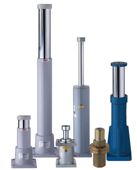
ITT Enidine heavy-duty hydraulic shock absorbers are designed to handle large impacts.
Machine builders are always on the lookout for ways to run equipment faster and increase throughput and productivity. However, components moving at high speeds often must decelerate and stop without damaging the equipment or payload. Otherwise, the consequences are excessive loads, vibration and noise that can compromise safety and machine reliability. Engineers can sometimes dampen motion with products like inexpensive elastomeric bumpers or simple air cushions. But these typically have a limited ability to absorb energy and decelerate objects.
Shock absorbers, in contrast, provide controlled deceleration by converting kinetic energy to thermal energy. In action, motion applied to a hydraulic shock absorber’s piston forces pressurized fluid through specially designed orifices. That restricts flow and generates heat which, in turn, transfers to the metal body and dissipates to the environment. They’re used in a wide range of applications, from automotive manufacturing and lumber processing to robots, cranes and packaging equipment.
Sizing a shock absorber is relatively straightforward. Several reputable manufacturers offer online calculators, but here are a few guidelines to help quickly come up with suitable products for a given task.
Manufacturers’ web sites and data sheets typically list products by parameters like stroke, usable velocity range, maximum amount of energy that can be absorbed per cycle, maximum force capacity, and the maximum propelling force it can handle, as well as dimensions and other relevant details. Before sizing a shock absorber, however, users first need to determine the relevant operating conditions, including the weight and velocity of the moving mass and how frequently the shock is loaded. For simplicity, let’s look at a linear-motion application and use Imperial units for the calculations.
Determine kinetic energy in the system from:
Ek = W/(722)(V2)
where Ek = kinetic energy, lb-in.; W = weight of moving mass, lb; and V = velocity of moving mass, in./sec. This equation represents the amount of kinetic energy that the shock absorber will convert to thermal energy on each impact.
Next calculate the work energy in the application, defined as the amount of energy an external device generates to move the load:
Ew = Fd(S)
where Ew = work or drive energy, lb- in.; Fd = drive force, lb; and S = stroke of the shock absorber, in. Note that Fd should not exceed the unit’s maximum rated propelling force. If it does, select a larger size and recalculate the work energy.
The next step is to calculate the total energy, Et (lb-in.) per cycle, shown as:
Et = Ek + Ew.
Again, if this exceeds the model’s energy-absorbing capacity, select a larger unit and recalculate the work energy. Otherwise, the shock’s temperature may rise beyond rated limits and critical internal components like hydraulic seals could fail.
If the application uses more than one shock absorber, divide the total energy Et by the number of shocks to determine the total energy per shock.
Then determine the total energy a unit must convert in one hour. That’s because even though a shock might absorb an acceptable amount of energy in a single impact, it might not be able to dissipate the generated heat if the cycle rate is too fast. Here, multiply Et by C, the total number of cycles per hour:
Etc = Et(C)
The device’s hourly capacity must exceed this calculated amount. If not, choose a larger absorber (and recalculate Ew if the stroke changes) or, possibly, add an external oil tank or a cooling device to help dissipate the heat.
Finally, consider the shock force, Fp (lb) in the application. Shock force, in essence, is the resistive force required by the shock absorber to stop the moving load:
Fp = Et/(Sη)
where S = the stroke of the shock absorber and η is the unit’s damping efficiency. While the efficiency can vary with the type and model, 85% efficiency is a good baseline for typical industrial shocks.
This is important when selecting a suitable shock absorber because the machine structure and mounting must have the necessary strength and rigidity to withstand the transmitted force. The efficiency of various units is measured by evaluating how much of the shock’s stroke is used for actual damping of the motion. Shock absorber efficiency increases as more energy dissipates over the stroke, and more-efficient products typically yield the lowest shock forces for a given stroke.
Considerations such as the machine’s structural integrity and the payload’s ability to withstand forces without damage are also key to successful damping configurations. And some applications or payloads may have specified g-load rating limits. For example, an operator housed in a large overhead crane must be protected from excessive g-forces.
Calculate this g-load from:
g = (Fp – Fd)/W
The above calculations help ensure that a given shock absorber meets all the application operating parameters. Again, make certain that the selected model matches or exceeds requirements for energy absorbed per cycle and per hour, as well as the shock force. Otherwise, it will likely cause damage or fail prematurely.
Filed Under: Fluid Power Basics, Slider