
David Marlowe • Owner/CEO • DMAR Technical Training and DMAR Business Centers USA
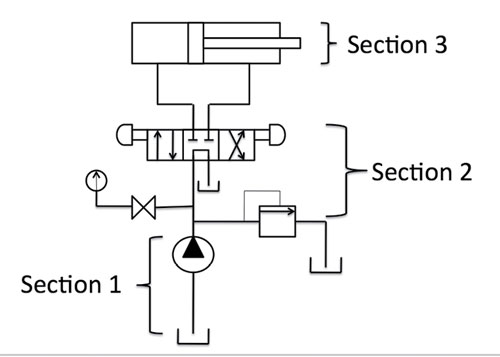 To date, we have discussed everything up to the discharge side of the hydraulic pump. In the last article we discussed the importance of a thoroughly thought-out, planned and executed proactive maintenance program and the benefits of maintaining the system instead of just operating it. Now, we will explore hydraulic circuitry by breaking the typical fluid power system into three general sections.
• Section 1: The transfer of mechanical energy into fluid velocity/fluid power
• Section 2: The regulation of fluid power through the use of various valves
• Section 3: The conversion of fluid power to mechanical energy by the use of an actuator
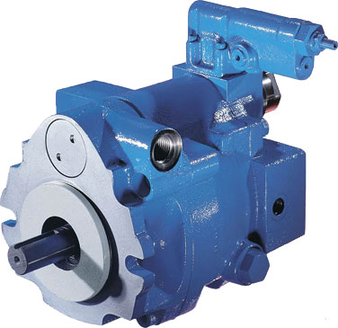
Image courtesy of Eaton Corp.
Section 1
• Power source: engine, electric motor, air motor
• Pump: vane, gear, rotary screw or piston
To understand how work is accomplished, one must first understand that it is nothing more than a transfer of electrical energy (electric motor) to mechanical energy (motor shaft to pump shaft) to fluid power (potential energy) to the cylinder/motor where the potential is converted to kinetic energy which provides work (Force × Movement = Work).
Energy being defined as: “the ability to do work”
Work is defined as: Force × Distance
In both dynamic and positive displacement pumps, the same action is accomplished by converting the mechanical energy to velocity into the fluid being pumped.
Positive displacement pumps, such as the gear, vane, rotary screw and piston types, are used almost entirely in industrial fluid power systems—where pressure is more important than volume.
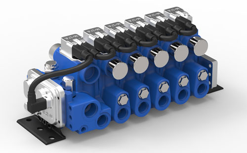
Image courtesy of Eaton Corp.
Section 2
• Pressure control valve: relief valve, pressure reducing or bypass valves
• Flow control valves: needle, non-compensated or compensated valves
• Directional control valves: 2-way, 3-way, 4-way or 5-way valves
Fluid power is only present in a system when the fluid is in motion and has a higher pressure than atmospheric. The amount of fluid power flowing in a pipe is directly proportional to its gauge pressure (measured in psi) and the rate of its flow (measured in gpm).
Various valves are used to regulate maximum pressure and flow rate. Pressure control valves include the relief valve (safety), pressure reducing and bypass valves. Flow control valves regulate the flow by restricting the flow such as the needle or flow control valve.
In a system using a cylinder, the flow must be directed to either side of the piston to allow the piston to extend or retract the cylinder rod. This action can only be accomplished by reversing the flow to each side of the piston. Here, a directional control valve—which is 2-way, 3-way or 4-way—is used.
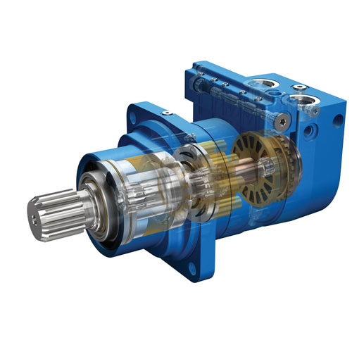
Image courtesy of Eaton Corp.
Section 3
• Mechanical power outlet: hydraulic motor, cylinder or rotary actuators
Because fluid power is not often used in its fluid state, it must be converted into mechanical energy to accomplish work either in a linear or rotary motion.
Fluid from the pump is converted into motion to complete the work. Cylinders are the most common choice, as they are used in linear applications. In rotary applications, users most often use hydraulic motors, which are available in gear, vane and piston styles, as well as the less commonly used gerotor or gerolor (orbital or roller star). The least common component is the rotary actuator, which is specifically used in high-torque, heavy-duty motion applications.
The simplest hydraulic system
A simple jacking system (bottle jack) is a hydraulic system that creates a high force (100 tons) at a very slow speed. The primary function of the bottle jack is to multiply and transmit force.
A one-piece unit, the jacking system consists of a reservoir, hand pump, ram and valving—all contained in a common enclosure (housing). Although the bottle jack is a basic hydraulic system design, it transfers energy from the energy source to the work piece just like the more advanced hydraulic systems. 
DMAR Technical Training
dmartechtraining.biz
Images courtesy of Eaton Corp.
Filed Under: Fluid Power Basics, Fluid Power World Magazine Articles, Pumps & Motors, Valves & Manifolds