
Oil coolers maintain balance in a
hydraulic system by cooling down
the energy input that the system
does not consume, helping to extend
hydraulic system and oil life,
operating time, and efficiency.
Typical hydraulic systems consisting of pumps, hydraulic lines, valves, and actuators all have inefficiencies. Even a well-designed hydraulic system will have inefficiencies when converting mechanical energy into fluid power. These issues, in addition to design and operational inefficiencies, transform some of the input power into heat. The entire system will overheat if this heat load is not dissipated. Extreme temperatures cause the fluid to overheat, reducing viscosity and eventually breaking down the fluid properties. This leads to damaged seals, bearings and excessive wear on pumps and other components. A properly sized oil cooler is required in the hydraulic system to avoid heating problems and expensive downtime due to system failure.
Oil coolers maintain balance in a hydraulic system by cooling down the energy input that the system does not consume, preferably at the system’s ideal working temperature, which is when the oil’s viscosity and the air content comply with recommended values.
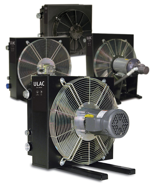
Different models of air oil coolers are designed for use with mobile and industrial machinery, with mobile equipment relying more on DC motors while industrial coolers usually use AC motors. Air oil coolers maintain temperature balance to prevent issues such as poor lubricating properties, internal leakage, a higher risk of cavitation, damaged components, etc. Overheating leads to a significant drop in cost efficiency and environmental consideration.
The correct working temperature produces a number of economic and environmental benefits, including extending hydraulic system and oil life, increasing operating time and reducing shutdowns, reducing service and repair costs, and increasing overall efficiency.
Understanding heat load
One of the key parameters in designing a hydraulic system is understanding and determining the heat load. Typically, designers estimate this by using a rule of thumb that heat load should be 30% of the installed system input power. Although this is not an ideal method, it is a widely accepted industry practice, especially when designing a new system when true losses are unknown until after it is built. The actual heat load can be determined precisely in a newly built or existing hydraulic system by conducting a simple heat load test.
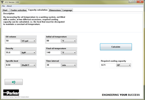
A screen capture of heat load calculation software from Parker Hannifin.
The test can be conducted on an existing hydraulic system by measuring the rise in temperature of a specific volume of fluid in the tank under full load conditions for a measured time period. This increase in fluid temperature is converted to heat that needs to be dissipated by a cooler.
P=(V x ΔT x Cp x ρ) / (Δt x 317.3)
Heat Load P = in hp
Volume of Fluid V = in gal
Temperature Rise ΔT = in 0F
Specific Heat Cp = in Btu/lb 0F
Density ρ = in lb/ft3
Time of test Δt = in min
Heat load in horsepower = 1.341 x heat load kW
Note: Heat dissipation through radiation of the hydraulic tank is not considered for this calculation.
Once heat load is determined, a cooler can be sized based on other parameters, such as fluid flow rate, media temperature entering the cooler and desired maximum fluid temperature. For precise heat load calculations, it is important to know fluid properties such as specific heat and density.
Parker Hannifin offers an air-oil cooler software program that enables users to easily calculate heat load once the above information is obtained from testing. This information can be used to size an appropriate air-oil cooler using the same software program.
In addition, brazed plate water-oil coolers can serve as an alternate option to air-oil coolers, with the methods used to calculate heat load remaining the same for both cooler designs.
Parker Hannifin, Accumulator and Cooler Div.
www.parker.com/accumulator
Filed Under: Components Oil Coolers, Fluid Power Basics, Fluid Power World Magazine Articles