Fluid Power World

  • Home
  • Technologies
    • Hydraulics
      • Cylinders & Actuators
      • Filtration/Contamination Control
      • Fittings, Couplings & Adapters
      • Fluids
      • Fluid Conditioning
      • Hose & Tubing
      • Pumps & Motors
      • Related Technologies
      • Sealing
      • Sensors & Gauges
      • Valves & Manifolds
    • Pneumatics
      • Air Preparation & Regulation
      • Compressed Air Technologies
      • Cylinders & Actuators
      • End Effectors & Grippers
      • Fittings, Couplings & Adapters
      • Hose & Tubing
      • Sensors
      • Vacuum
      • Valves & Manifolds
  • Engineering Basics
  • Trending
  • Resources
    • Digital Issues
    • Pneumatics Tech Toolbox
    • Podcasts
    • Subscribe to Fluid Power World Print Magazine
    • Videos
    • Webinars / Digital Events
    • White Papers
  • Women in Engineering
    • Women in Fluid Power
    • Women in Engineering
  • Design Guide Library
  • Classrooms
    • Pneumatics Classroom
  • SUBSCRIBE

Compressed air fail: Optimized nozzles

By Paul Heney | February 6, 2023

Share
Fig. 1. This standard air wand is used for bearing cooling and was installed as a temporary measure 10 years ago. It was measured at 9 cfm.

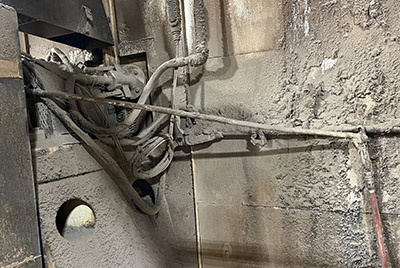
A building products company had constantly overheating bearings on some large fans induced draft in their process and decided to use compressed air to provide some extra cooling. On one fan bearing they installed a spare air wand and tied it in position with wires, so the nozzle pointed directly at the hot bearing, this was done as a temporary measure ten years ago. The trigger of the wand was wired open for continuous flow, the air consumption continuing without interruption, Fig. 1.

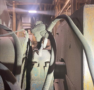
For the next fan bearing fix they had become aware of high efficiency compressed air nozzles, so they rigged up a cooler using a specialty nozzle to save energy, Fig. 2. This nozzle had a flexible goose neck used to position the nozzle to provide the best cooling. This again was a temporary measure, but years later the nozzle continued to blow.

Fig. 2. This optimized specialty nozzle was measured at 14 cfm and was running at much higher than rated pressure.

A compressed air assessment was done at the plant and the auditor decided to measure both nozzles. He was surprised to find that the standard air wand consumed 9 cfm while the optimized nozzle consumed 14 cfm, something he had not expected. A look at the installation showed that the standard wand was fitted with a pressure regulator, however, the optimized nozzle used unregulated line pressure. A look into the specifications of the optimized nozzle showed that the rated pressure for the nozzle was 70 psi, but it was running at 110 psi, consuming about 70% more than its catalog rating.

This exercise showed, if we must use compressed air flowing, we should not assume that optimized nozzles will actually save compressed air flow, all nozzles need to be installed correctly and fed with rated pressure.

It turns out that this bearing cooling was determined to be unnecessary, the nozzles were installed years ago but never removed when the bearings were changed. These two items were eliminated, reducing the compressed air load by 23 cfm and saving $4,000 in electricity costs annually.


Filed Under: Components Oil Coolers, Compressed Air Technologies, Pneumatic Tips


About The Author

Paul Heney

Current Digital Issue

  Easier access to more of our content Every other month, readers of Fluid Power World have access to our beautiful print and digital editions, where we share a selection of the best fundamentals content, technology news, case studies, and technical articles that cover the gamut of hydraulics and pneumatics system design. But we only…

Subscribe!

Fluid Power World is written by engineers for engineers engaged in designing machines and or equipment in Off-Highway, Oil & Gas, Mining, Packaging, Industrial Applications, Agriculture, Construction, Forestry, Medical and Material Handling. Fluid Power World covers pneumatics, mobile hydraulics and industrial hydraulics.

Fluid Power Design Guides

fluid
“fpw
EXPAND YOUR KNOWLEDGE AND STAY CONNECTED
Get the latest info on technologies, tools and strategies for Fluid Power Professionals.

RSS Featured White Papers

  • Moving fluid power forward
  • High-force linear motion: How to convert from hydraulic cylinders to electric actuators and why.
  • A technical comparison: Performance of pneumatic cylinders and electric rod actuators
Fluid Power World
  • Hose Assembly Tips
  • Mobile Hydraulic Tips
  • Pneumatic Tips
  • Sealing & Contamination Control Tips
  • About us
  • Contact Us

Copyright © 2024 WTWH Media LLC. All Rights Reserved. The material on this site may not be reproduced, distributed, transmitted, cached or otherwise used, except with the prior written permission of WTWH Media
Privacy Policy | Advertising | About Us

Search Fluid Power World

  • Home
  • Technologies
    • Hydraulics
      • Cylinders & Actuators
      • Filtration/Contamination Control
      • Fittings, Couplings & Adapters
      • Fluids
      • Fluid Conditioning
      • Hose & Tubing
      • Pumps & Motors
      • Related Technologies
      • Sealing
      • Sensors & Gauges
      • Valves & Manifolds
    • Pneumatics
      • Air Preparation & Regulation
      • Compressed Air Technologies
      • Cylinders & Actuators
      • End Effectors & Grippers
      • Fittings, Couplings & Adapters
      • Hose & Tubing
      • Sensors
      • Vacuum
      • Valves & Manifolds
  • Engineering Basics
  • Trending
  • Resources
    • Digital Issues
    • Pneumatics Tech Toolbox
    • Podcasts
    • Subscribe to Fluid Power World Print Magazine
    • Videos
    • Webinars / Digital Events
    • White Papers
  • Women in Engineering
    • Women in Fluid Power
    • Women in Engineering
  • Design Guide Library
  • Classrooms
    • Pneumatics Classroom
  • SUBSCRIBE