Fluid Power World

  • Home
  • Technologies
    • Hydraulics
      • Cylinders & Actuators
      • Filtration/Contamination Control
      • Fittings, Couplings & Adapters
      • Fluids
      • Fluid Conditioning
      • Hose & Tubing
      • Pumps & Motors
      • Related Technologies
      • Sealing
      • Sensors & Gauges
      • Valves & Manifolds
    • Pneumatics
      • Air Preparation & Regulation
      • Compressed Air Technologies
      • Cylinders & Actuators
      • End Effectors & Grippers
      • Fittings, Couplings & Adapters
      • Hose & Tubing
      • Sensors
      • Vacuum
      • Valves & Manifolds
  • Engineering Basics
  • Trending
  • Resources
    • Digital Issues
    • Pneumatics Tech Toolbox
    • Podcasts
    • Subscribe to Fluid Power World Print Magazine
    • Videos
    • Webinars / Digital Events
    • White Papers
  • Women in Engineering
    • Women in Fluid Power
    • Women in Engineering
  • Design Guide Library
  • Classrooms
    • Pneumatics Classroom
  • SUBSCRIBE

Compressed air fail: Ventilation design

By Paul Heney | December 23, 2022

Share
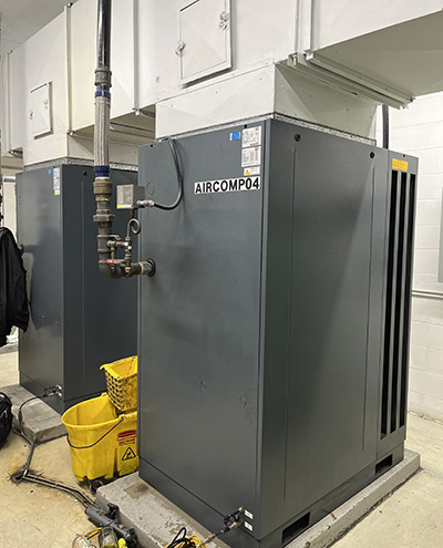
Fig.1. These air-cooled compressors are running hot, loading the associated air dryers excessively because the ventilation designer did not address all the sources of heat in the room and the source of the cooling air.

A plastics manufacturer was having constant trouble with his desiccant air dryers. No matter what he did, they would constantly set off dewpoint alarms, which was very annoying. He called in a compressed air auditor to have a look.

The auditor shot temperatures and found that the discharge of the compressors was too hot. Outputs exceeding 120° F contained more water than the air dryers were rated to process, with moisture levels increasing by about double for every 20° F increase. The auditor measured the temperature of the cooling air, this was also excessive, even though the temperature outdoors was only 30° F.

The auditor pointed to the compressor room ventilation inlet duct — it was coming from the plant, where temperatures were near 90° F. He directed the Maintenance Manager’s attention to two electric vacuum pumps in the room that were radiating significant amounts of heat. And he pointed up to the hot air ducting that was connected to the compressor. The large hot surfaces were radiating a significant amount of heat into the room, raising the ventilation air temperature to excessive levels.

The ventilation system designer had not accounted for all sources heat radiation within the room, had chosen a poor source of cooling air, and had no cross ventilation. The compressors were overheating because the cooling air was too hot, overloading the air dryers. Clearly, this was the cause of the constant alarms.

At this site, it was relatively easy to install additional ventilation with thermostatic control to temper the room with cool outside air, but not to subject equipment to freezing winter temperatures. Once this was in place, the Maintenance Manager finally had peace again.


Filed Under: Components Oil Coolers, Compressed Air Technologies, Pneumatic Tips


About The Author

Paul Heney

Current Digital Issue

  Easier access to more of our content Every other month, readers of Fluid Power World have access to our beautiful print and digital editions, where we share a selection of the best fundamentals content, technology news, case studies, and technical articles that cover the gamut of hydraulics and pneumatics system design. But we only…

Subscribe!

Fluid Power World is written by engineers for engineers engaged in designing machines and or equipment in Off-Highway, Oil & Gas, Mining, Packaging, Industrial Applications, Agriculture, Construction, Forestry, Medical and Material Handling. Fluid Power World covers pneumatics, mobile hydraulics and industrial hydraulics.

Fluid Power Design Guides

fluid
“fpw
EXPAND YOUR KNOWLEDGE AND STAY CONNECTED
Get the latest info on technologies, tools and strategies for Fluid Power Professionals.

RSS Featured White Papers

  • Moving fluid power forward
  • High-force linear motion: How to convert from hydraulic cylinders to electric actuators and why.
  • A technical comparison: Performance of pneumatic cylinders and electric rod actuators
Fluid Power World
  • Hose Assembly Tips
  • Mobile Hydraulic Tips
  • Pneumatic Tips
  • Sealing & Contamination Control Tips
  • About us
  • Contact Us

Copyright © 2024 WTWH Media LLC. All Rights Reserved. The material on this site may not be reproduced, distributed, transmitted, cached or otherwise used, except with the prior written permission of WTWH Media
Privacy Policy | Advertising | About Us

Search Fluid Power World

  • Home
  • Technologies
    • Hydraulics
      • Cylinders & Actuators
      • Filtration/Contamination Control
      • Fittings, Couplings & Adapters
      • Fluids
      • Fluid Conditioning
      • Hose & Tubing
      • Pumps & Motors
      • Related Technologies
      • Sealing
      • Sensors & Gauges
      • Valves & Manifolds
    • Pneumatics
      • Air Preparation & Regulation
      • Compressed Air Technologies
      • Cylinders & Actuators
      • End Effectors & Grippers
      • Fittings, Couplings & Adapters
      • Hose & Tubing
      • Sensors
      • Vacuum
      • Valves & Manifolds
  • Engineering Basics
  • Trending
  • Resources
    • Digital Issues
    • Pneumatics Tech Toolbox
    • Podcasts
    • Subscribe to Fluid Power World Print Magazine
    • Videos
    • Webinars / Digital Events
    • White Papers
  • Women in Engineering
    • Women in Fluid Power
    • Women in Engineering
  • Design Guide Library
  • Classrooms
    • Pneumatics Classroom
  • SUBSCRIBE