
Learn how to reduce the damaging side effects of noise and vibration caused by hydraulic power units in industrial settings.
By Josh Cosford, Contributing Editor
There’s nothing quite like the high-pitched racket emitting from a hydraulic power unit. The combination of noises originates primarily at the hydraulic pump, but secondary harmonics and reverberations contribute to a cacophony, unlike any other machine noise. The telltale hydraulic whine is the bane of machine operators forced to mentally block the press/shear/extruder noise, raising their neck hair.
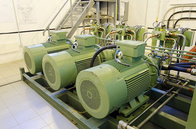
Courtesy of Adobe Stock
The hydraulic power unit noise problem isn’t lost on engineers and designers. As a result, manufacturers have designed components to be inherently smoother and quieter. Hydraulic designers may also select components less likely to contribute to the raucous sound. At the same time, technicians have options to ensure that as little of the vibrations as possible translate into annoying and potentially hazardous noise.
Pressure from the pump means turbulence
Much of the attention applied to noise and vibration reduction is rightfully aimed squarely at the hydraulic pump. Most hydraulic pumps transform incoming mechanical energy into hydraulic energy discretely. Rather than feed a continuous stream of hydraulic fluid into the circuit, a pump sends individual packets of pressurized fluid to the outlet. Each discrete bundle of compressed hydraulic fluid blasts forth into the pressure line with a tiny wave of pressure.
No pump perfectly transmits pressure without bumps, corners, or turbulence, and each impedance encourages vibration and noise. More often than not, lens plates, gears, vanes, ports, and pistons all contain sharp edges, abrupt turns, or choked flow paths. The movement of fluid through a pump is far from laminar. Even if every metal pump component were chamfered, bevelled and honed, the resulting reduction in noise generation would likely be offset by the same reduction in efficiency.
From a design and installation perspective, the manufacturer holds responsibility for effort and ingenuity that must result in quieting solutions. In addition, a manufacturer must balance the varied demand asked of their pumps, which requires efficient operation across various pressure and flow outputs. A pump may be designed to limit pressure pulsations at 1,800 rpm and 3,000 psi but could do so poorly when run at 3,450 rpm and 1,000 psi, for example.
The pump pulsation is the primary NVH (Noise, Vibration & Harshness) driver. Each of those hydraulic energy bundles discharged from a pumping element (like a piston) or chamber (like vanes and gears) emits a pulse, and the frequency of those pulses dictates the timbre of the hydraulic noise. The frequency is a product of the prime mover rpm and the number of elements or chambers. A 9-piston pump running at 1,750 rpm results in 1,5750 pressure signals per minute. In acoustic terms, the pump’s fundamental frequency is 262.5 Hz (15,750 divided by 60 seconds in a minute) while also emitting high amplitude harmonics at 525 and 787.5 Hz.
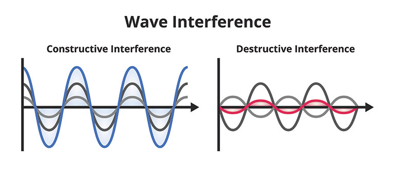
Figure 1. A look at different types of noise wave interference. When sound frequencies overlap with peaks atop peaks, the sound pressure level increases. Depending on the mass, size, shape and elasticity of the object adding the resonance, the increase could range from barely audible to ear-splitting.
By the same token, a pump may produce harmonics anywhere within the audible spectrum between 20 Hz and 20,000 Hz (or 11,500 Hz as tested for this author’s “old man ears” *see sidebar). Of course, we all know these harmonics combine to make annoying sounds, especially the harmonics falling between 1,000 & 5,000 Hz, where people’s hearing is most sensitive.
* I’ve had my ears tested, and it appears that years of loud music in living rooms, cars and headphones have damaged my ears and lobbed off an entire octave of sound above 11,500 Hz. One of my hobbies is music production, so I’m slightly disadvantaged when mixing and mastering. However, there is one unexpected advantage to these old man ears – taking advantage of young ears. Tone generators downloaded on my phone make for a great prank to walk around blaring 15,000 Hz of piercing noise unheard by myself. It quickly clears the living room of teenagers lazing about on their electronics.
Looking at other sources of noise and vibration
Moreover, it’s essential to understand the rest of the hydraulic power unit’s contribution to amplifying noise. The prime mover and pump contribute most of the fundamental frequencies, but anything and everything attached to the power unit transmits and emits vibration and sound. An acoustic engineer could spend many times the cost of the power unit calculating and estimating how loud the power unit might be and at what frequencies. But sometimes, the particular sound and harmonics are unpredictable.
Let’s take the reservoir, for example. Its combination of welded plates, cut-outs, holes, and accessories sometimes augment the fundamental and harmonic frequencies emitted by the pump. Every physical body has a natural harmonic frequency, and sometimes those harmonics can overlap. When sound frequencies overlap with peaks atop peaks (Figure 1), the sound pressure level increases. Depending on the mass, size, shape, and elasticity of the object adding the resonance, the increase could range from barely audible to ear-splitting. When the dice fall against your favor, the reservoir may literally ring with resonance.
As much as possible should be done to isolate the pump from any possible harmonic contributor. The most obvious point of shared vibration is where the pump/motor attaches to the reservoir. Two traditional methods are common — vertical (in-tank) and horizontal (tank top). The L-Shape and elevated tank make great choices, but the prior two choices far outnumber the latter.
With vertical motor power units, the pump resides below the oil level through a large hole in the top surface where the bell housing attaches using (typically) four bolts in its flange. Any vibration in the pump or motor transmits directly to that top plate and any other metal welded, clamped, or bolted to the tank. The horizontally mounted pump uses a C-Face motor that directly couples the pump using a similar bell housing. However, these units employ foot mounting via the motor, but the opportunity still exists for the pump’s vibrations to transmit through the bell housing and motor to the tank top surface as well.
If you’ve designed or fabricated a hydraulic power unit, you know we don’t just weld or bolt the pump/motor group together and hope for the best. The damping of sound and vibration starts at the connection between the pump and motor. The drive couplers transfer the power from the motor to the pump and use a rubber insert tightly sandwiched between the couplers to reduce the vibration transfer from one to the other. The couplers and insert also help with shaft misalignment.
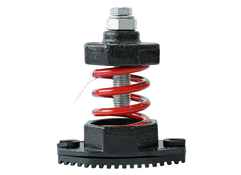
Figure 2. Vibration isolators manufactured of an elastomer and spring help reduce an assembly’s natural frequency, thus damping noise and vibration.
Any time you introduce elasticity to an interface, you reduce the natural frequency of the assembly. Elastomers (or actual springs) should be chosen with a natural frequency at least half that of the pump’s rotational frequency. For example, your 1,800 rpm motor’s 30 Hz frequency would best due with isolators offering 10 Hz or less. This theory applies not only to the coupler insert but the anti-vibration mounting feet (Figure 2) used to attach a horizontal pump/motor to the reservoir.
The individual mounting feet seen in Figure 2 are less prevalent in applications where the motor fully supports the pump via the bell housing. However, when foot-mounted pumps sit directly on the reservoir top and the motor is asked only to support its own weight, these act as a vibration buffer. For bell housing-mounted pumps, the solution is two-fold. First, rubber gaskets mounted between the motor C-Face and the bell housing provide a barrier for vibration and sound (and also work well in vertical pump power units). The motor is best mounted using vibration-damping bars as an additional isolation layer. Consisting of a thick rubber pad sandwiched between two steel bars, the damping bars allow the technician to bolt the pump to the top bar while welding the bottom directly to the tank.
Taking plumbing into consideration
Of course, other components transmit sound and vibration besides the pump/motor group. You’d be surprised at how much sound energy transmits through plumbing, such as tubes and hoses. The steel of the tube or hose reinforcement vibrates readily in tune with specific harmonics, although the effect is mitigated by long lengths of plumbing, which have a lower natural frequency.
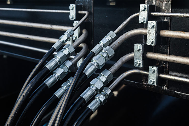
Figure 3. Having all hydraulic hose or steel tube in a high-pressure hydraulic system is a recipe for noise. Using a combination of steel tube with hose reduces cyclical radial expansion over a long hose but also isolates the tube from direct machine vibrations.
However, with long plumbing runs, using only tube or hose for the entire length makes for an efficient radiator of sound energy, especially when harmonics overlap with its fundamental frequency. The ideal configuration for sound damping through conduits is to run the longest part of the plumbing with a tube and then each end terminating with short hose assemblies. The tube sandwich technique not only reduces cyclical radial expansion over a long hose but also isolates the tube from direct machine vibrations.
Sound emits not only from vibrating components but also through the hydraulic fluid itself. In fact, liquids transmit sound energy more efficiently than does air, so anywhere a conduit filled with oil goes, so too does pump noise. The creative use of pressure line accessories helps to dampen and absorb noise as it leaves the pump. Hydropneumatic accumulators charged to around 1/3 operating pressure and teed into the pressure line provide a damper to absorb pressure waves, thereby reducing noise energy.
Noise may come from unexpected sources, as well. One application took our team days to discover and remedy the solution. It was a standard hydraulic power unit with a vertical pump motor mount attached to an 80-gal reservoir. Mounted atop was a kidney loop circuit for filtration and cooling, which included a liquid-to-air cooler. We narrowed the noise down to the cooler, which was constructed using bent sheet metal to shroud the heat exchanger. Our choice of pump, along with steel tubing, created a harmonic resonance of the sheet metal.
Our fix was ad hoc, and through elimination, we changed to a different pump displacement, replaced the tube with hose, and then added two 90° elbows in series at the cooler inlet port. What previously gave the office workers headaches from the piercing noise morphed into your standard hydraulic whine. Even when all noise-reduction measures are heeded, sometimes the stars align to make a cacophony unintentionally with no way to predict the result.
Filed Under: Components Oil Coolers, Engineering Basics, Trending