
By Jeremy Beale
The recent article, Design Concepts for Open-Circuit Architectures, discussed some options for power-limiting circuits. Now let’s consider flow amplification.
Flow-divider hydraulic press concept
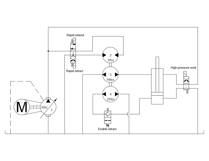
One approach for reducing valve size and losses is to amplify flow between the directional valve and cylinder. Conceptually, a flow divider is used as a “step-down” transformer, using energy from a high-pressure stream to generate low-pressure streams with far higher flow rates. Pressure will increase when the cylinder encounters load. At that point, the flow divider will stop rotating and the rapid motion 4-way valve can be centered. Then the high-pressure work valve should be opened to complete extension. During rapid retract, flow divider rotation will be reversed. Possible pump/motor displacements for a 130 gpm press are shown nearby.
The flow-divider concept addresses several problems of a traditional high-low circuit.
a. The primary pump operates near maximum pressure, max displacement and max speed for the entire working cycle. This avoids the problems associated with inefficient low-power operating conditions.
b. Throttling losses are minimized, because only a small portion of flow must pass through the directional valves.
c. Idling losses are minimized, because the flow divider will stop rotating without a pressure source.
d. Proportional control is cheap to implement with a relatively small directional valve.
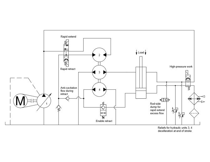
Flow-divider with compensated pump
However this design also introduces new problems.
a. The flow divider cannot stop quickly. It should coast to a stop, requiring relief valves to transfer excess flow back to tank.
b. The flow divider size cannot be matched precisely to the size of the cylinder. Some imbalance of flow will result. This imbalance must be addressed with additional valves, as is shown in the accompanying circuit with compensated pump. Note that the circuit assumes Unit 4 is slightly oversized relative to Unit 3 and the cylinder area ratio. This oversizing creates an “excess flow” during extension, which passes back to tank through the two-way rod-side dump valve. During retraction, Unit 4’s oversizing causes a potential cavitation problem in the cylinder’s bore end. Return line flow from Unit 1 is brought over via check valves to prevent this cavitation.
c. The flow divider cannot accelerate quickly. It may take 1 to 2 seconds to reach full speed. This delay may be undesirable in some applications requiring rapid cylinder response. However the delay may be advantageous when considering decompression shock. The combined inertia of Units 2, 3 and 4 will prevent the transmission of shock when switching from extension to retraction.
A bent-axis piston pump is recommended for Unit 2. This type will reduce energy loss for several reasons: Bent-axis piston motors typically achieve efficiencies of 92% or greater; and they can operate up to 6,000 psi, whereas gear/vane motors are typically limited to 3,000 psi or less. Higher pressures imply lower flows required to transmit any given quantity of hydraulic power. Lower flows imply reduced throttling losses through the directional valves.
Vane-type or gear-type pumps are recommended for Units 3 and 4. These are typically the least expensive options for pressures below 1,000 psi. Also these pumps should be specially configured for optimal efficiency at low pressure. Manufacturers such as Geartek offer large multi-section gear pumps optimized for 500 psi operation (up to 200 gpm per section). For applications with flows over 400 gpm, bidirectional screw (progressing cavity) pumps may be more practical than using multiple sets of tandem gear pumps.
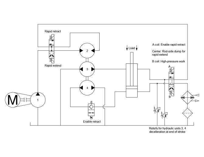
Flow-divider with fixed-delivery pump
Note that the filter and heat exchanger are shown receiving flow from the high-pressure work valve. This is a simplification for convenience. Other return lines can also be fed to the heat exchanger, such as the rod-side dump valve and the rapid extend valve return.
If a fixed-delivery pump is selected for Unit 1, several changes should be made to the hydraulic circuit:
a. The directional valves are configured in series rather than parallel.
b. The rod-side dump valve for rapid extend excess flow is not necessary. This function is provided by the center position of the 4-way directional valve.
c. Anti-cavitation checks providing flow during rapid retract are not necessary. The “A” coil of the 4-way directional valve will be energized during rapid retract, which will balance the flows entering and exiting the cylinder. Cavitation will not occur.
Initial cost estimates suggest the flow-amplification concept (either fixed-delivery or pressure-compensated) becomes less expensive than a traditional high-low design above 60 to 80 gpm traditional pump flow (such as a conventional torque-limiting pump or tandem-pump high-low circuit). As flow rate increases above this point, a flow-amplification design becomes increasingly cost-effective compared to traditional options.
If rapid response is needed from the flow divider, some changes are required for Unit 2. First, it must be up-sized. Second, it must become variable displacement. Full displacement would be used at low speed. Fractional displacement would be used at high speed. The displacement change would ideally follow a continuous “constant-power” curve. This curve can be mirrored by the controller of Unit 1 in a variable pump circuit. However a more-economical alternative would be a “two-speed” hydraulic motor for Unit 2. This type of motor has two discrete “high-low” displacements, typically selectable by solenoid or pilot pressure.
Filed Under: News, Pumps & Motors, Valves & Manifolds