
From a fluid power design perspective, the circuit and subsequent major components take the majority of the focus. Actuators, valves, pumps and conditioning components rightfully take center stage, leaving accessory components out of the design stage and left for the technicians to worry about during fabrication. However, factoring all parts – no matter how insignificant – makes the difference between a refined machine and a hack job.
Stauff clamping systems
Tidy plumbing, of course, often makes or breaks the appearance of a machine. Floppy hoses hanging all over the machinery, or tubes not fixed and supported, make a machine look unprofessional and cheap. Planning out the method of fixing plumbing to the beams, columns and panels scores points with the customer, so be sure to make it part of the planning phase.
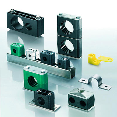
Pipe and tube block clamps combine rigid plastic with steel plates either welded, clamped or bolted to the machine as required. The clamp bodies are most common in single and dual groups, for clamping one tube, pipe or hose, or with two conduits run in parallel. Although bodies come in a single or double group, the plates blocks are mounted to go in single, dual or multiple widths, allowing two, four or many parallel lines run together.
Weld plates permanently fix the tubing to the surface on which it mounts. Welded at strategic locations around the machine with a given distance between the clamps based on the type of conduit (hose, tube or pipe), the conduit diameter and the conduit thickness. Heavy wall pipe or tube of large diameter are more rigid, allowing more significant gaps between clamps compared to smaller diameter conduits. The documentation of the clamp manufacturer will provide the maximum allowable distance, but for example, ½ in. OD tube can span only just over three feet while 3 in. OD tube gaps nearly twelve feet.
The clamp assemblies mount to the bottom plate, itself usually welded. However, rail-mounted clamps are popular where the machines run other wires, plumbing or conduits not related to the hydraulics itself, such as an injection molding machine running electrical cables, coolant and airlines.
The clamp body is a “C” shaped pair of injection molded hard plastic components. The bottom body rests on the plate before placing the conduit into the pocket. The top body slips over the pipe before fixing the cover plate atop the assembly, and then either one or two bolts run down through the assembly and tighten against the plate.
The options available for clamping systems is dizzying, and product catalogs run well over a hundred pages. With much thought put into, what appears on the surface, a simple product highlights the importance of intelligent consideration of your machine’s plumbing. Every possible combination suitable to any conceivable machine gives you no excuse not to place plumbing clamping systems at the forefront of machine design. Your customers will thank you.
Filed Under: Hose & Tubing, Hose Assembly Tips