
 David Marlowe • Owner/CEO • DMAR Technical Training and DMAR Business Centers USA
When designing a hydraulic system, it is important to understand the difference between cavitation and aeration—and understand the damage they can create.
As previously discussed in our April issue, it is critical to maintain proper fluid levels in the reservoir to ensure the Net Positive Suction Head Available (NPSHA) is greater than the Net Positive Suction Head Required (NPSHR) by the pump.
Anytime the NPSHA is equal to the NPSHR, the flow instabilities in the fluid moving to and through the pump will be affected to the point cavitation can (and will be) generated.
Aeration is a process where air is circulated with, mixed with or dissolved in the hydraulic fluid. It is created when air leaks into the system through the pump seals, pipe fittings and unions, which are all areas where air leakage is common.
Aeration accelerates degradation of the fluid and causes damage to system components through loss of lubrication, overheating and burning of seals.
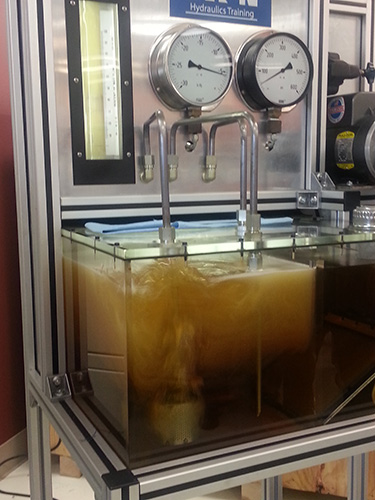
Although you can not see cavitation, a demonstration at Eaton’s training facility in Maumee, Ohio, shows an extreme example of the effects of excessive air in hydraulic fluid.
Cavitation, on the other hand, is the formation of gas bubbles that create vapor cavities in a liquid. It occurs when the gas bubbles in the liquid are subjected to rapid changes of pressure. This higher pressure causes the air bubbles to implode, which generates an intense miniature water hammer (shock wave). This shock wave creates significant wear as the gas bubbles implode on or near a metal surface, causing cyclic stresses through repeated implosions.
The result of these implosions will cause surface fatigue and damage to the metal surfaces. This type of wear is called “inertial cavitation.”
Cavitation occurs when the volume of fluid demanded by any part of a hydraulic circuit exceeds the volume of fluid being supplied. This causes the absolute pressure in that part of the circuit to fall below the vapor pressure of the hydraulic fluid. This will result in the formation of gas bubbles.
The difference between the two is in how the air is getting into the system. Cavitation is caused by NPSHA, and can be stopped by simply slowing the fluid flowing through the system. If the problem is aeration, on the other hand, you have to locate and isolate the air leaking into the system, so resolving the problem can be more time-consuming. The damage by both is equal, however.
The following are the most common detectable symptoms that give warning of cavitation and aeration:
Abnormal noise in hydraulic systems is often caused by aeration and/or cavitation. Air in the hydraulic fluid makes a banging or knocking noise when it experiences high and low system pressures as it circulates through the system.
High fluid temperatures above 180° F (82° C) are detrimental to system operation and will damage seals and accelerate degradation of the fluid. High temperatures can be caused by anything that reduces the system’s capacity to dissipate heat (low reservoir level) or increases its heat load (air generates heat when compressed).
In addition to damaging seals and reducing the service life of the hydraulic fluid, high fluid temperature can cause damage to system components through boundary lubrication as a result of excessive thinning of the oil film (lower viscosity index), which in turn causes full film lubrication loss.
Slow operation, or a reduction in system performance, is often the first indication that there is something wrong. In a hydraulic system, flow controls speed and response. Therefore, a loss of speed indicates a loss of flow.
Other symptoms include erratic actuator and valve movement.
Consequences of cavitation in a hydraulic system can be serious. Cavitation causes metal erosion, thus damaging the system components and contaminating the fluid. Cavitation can also cause mechanical failure of system components.
Cavitation can occur anywhere within the hydraulic circuit; however, hydrodynamic cavitation commonly occurs at the pump. The pump suction line between the reservoir and pump should be open and not restricted. If the pump has an inlet strainer or filter, it is important to prevent it from becoming clogged. A partially closed suction valve or restricted intake line will cause the velocity of the fluid in the intake line to increase, causing the boiling temperature of the fluid to decrease as the fluid pressure goes below vapor pressure. This will vaporize some of the fluid molecules.
The following are common causes of aeration and cavitation, so monitor your system for any of these improper designs:
1. Restricted fluid flow to pump
2. Loose connection or fittings on suction line
3. Low hydraulic fluid level and/or low NPSHA
4. Excessive pump speed; be sure to check specifications of the pump and motor
5. Incorrect hydraulic fluid or wrong oil viscosity
6. Foaming oil and/or low or old oil levels
7. Clogged reservoir air breather vent
8. Too low of an oil temperature
9. Damaged or worn pump
The damage caused by unresolved cavitation to a hydraulic system can be extremely expensive and cause extensive downtime. Prevent this problem with proper system design and maintenance. And always, listen to your hydraulic system. A rattling or knocking noise is not the sound of a welcome visitor.
DMAR Technical Training and DMAR Business Centers USA
www.dmarbusinesscenters.com
Filed Under: Fluid Power World Magazine Articles