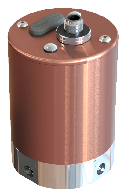
Some electropneumatic pressure regulators work by combining three important elements: the mechanical valve, the solenoid, and the controller.

The mechanical valve is comprised of the valve body, spring, and spool. The valve body is typically machined from aluminum or brass. It includes a port for the unregulated air to enter the valve. Internally machined is a pilot passage that directs the air around and against the spool. The spool is a precise formed part that slides into a cavity within the valve body. A spring is then placed on top of the spool sealing it against the seat of the cavity. The final part of the mechanical valve is the port machined for the now regulated air to move into the rest of the circuit.
When referring to the solenoid, we are talking about the product of the coil, tube, and armature. The coil is formed by wrapping of copper wires into a spiral. This spiral in size and shape determines the performance of the output of the solenoid. With the coil energized, it creates an electromagnetic field to propel the armature in a linear motion. The coil then slides over the tube, which contains the armature made with special attention to the iron quality to ensure performance. Having the solenoid slide over the tube allows the valve to be serviced as the coil or tube can be replaced if it reaches end of life. The armature moves out in proportion to the current or voltage applied from the controller.
The controller — either a programmable logic controller (PLC), integrated on the valve, or a separate controller from the valve manufacturer — follows the same logic. The valve is programmed by having a current or voltage amount set to a proportional value of pressure. The controller requires an analog signal, from a pressure transducer for example, that is a voltage or current value. The controller then processes this signal and determines based on the program the output signal to the valve. The signal is then a voltage or amperage that moves the armature a linear amount increasing or decreasing the spring force on the spool.
The marriage of these three parts and their sub-assemblies creates a near real time adjustment in the performance of the pneumatic circuit’s force or torque. When designed and implemented correctly the system can be highly efficient minimizing input air and electricity, while maximizing the output of the system.
Filed Under: Air Preparation & Regulation, Fluid Power Basics, Pneumatic Tips