
In Hydraulic Symbology 201, I discussed directional valve symbols from basic construction to valve transitions. For the most part, these symbols pertain to industrial stack valves, although cartridge valve symbology is similar. When the stack valve — aka CETOP, ISO or “D-something” valve — is drawn in a circuit, however, it looks much different.
Shown below, Figure 1, is a simple circuit employing two cylinders assisted by various accessory valves. I haven’t covered the design and function of pressure, flow or check valves, so ignore them for now. What’s important to observe is the relatively linear method of drawing each subcircuit, with the pump pushing through all the valves and then eventually onto the cylinder.
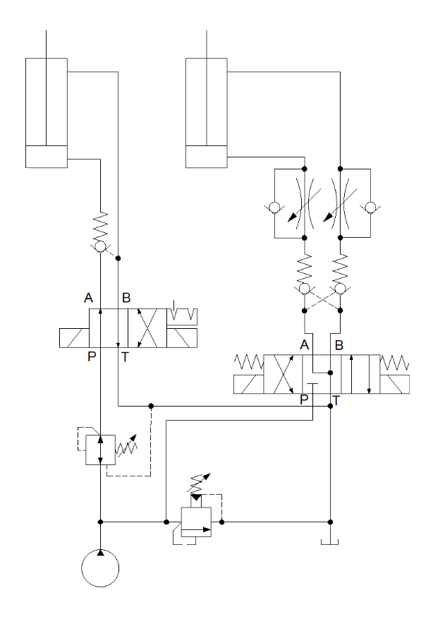
Figure 1. Standard circuit
The valves of this hydraulic system are plumbed together individually with hose, tube and fittings, but their physical relationship is not defined. The relief valve could be attached to the pump or it could be a room away. The directional valves could be at opposite ends of the machine and both lead to cylinders that work in tandem. There’s no way to know, and from a design standpoint, how it is plumbed is irrelevant to the circuit drawing.
Want more symbology content? Download our 45-page Symbology Building Blocks e-book now.
A circuit made from stack valves, Figure 2, is a different animal, and you can be sure they will be plumbed as you imagine it should be. Each component of the valve stack is sandwiched together and bolted tightly into the manifold with tie-rods or socket head cap screws. The manifold is always on the bottom, and the directional valve is nearly always fixed atop.
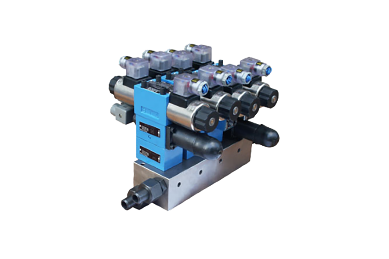
Figure 2. Stack valves (Image courtesy of Hengli America)
The drawing below shows the stacked valves interfacing and separated by a boundary line, which you’ll remember is the broken-dash line I explained way back in Symbology 101. Figure 3 shows the same 2-position valve on the left with the 4/3 valve again on the right. Fluid enters the left side of the manifold at the P port and feeds oil equally to each valve station. This manifold has two stations, but I’ve seen up to as many as 16 stations machined into a single bar.
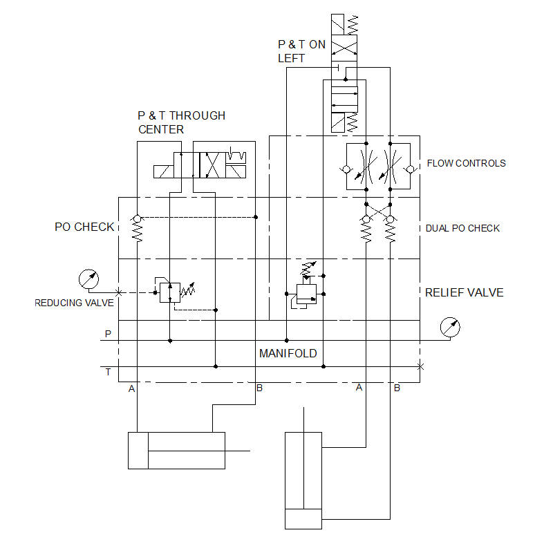
Figure 3. Stack valve circuit
The valves are plumbed in parallel, so either sub-circuit has equal access to flow. The left-side stack uses a method of drawing the directional valve with the pressure and tank lines running through the center, with pressure on the left-center and tank on the right-center. In the neutral position, fluid travels up through the reducing valve, through a hole in the pilot operated check valve and up through the directional valve.
Because the valve is at the top and is a 2-position valve, fluid goes straight through and back down again, where it passes through the PO check itself, down through a drilling in the reducing valve, through the manifold and out work port A. It sounds like a lot going on when you spell it out, but it’s ready quite simple. Each and every component in a stack will flow fluid through one or more ports so long as the directional valve is actuated.
Stack valve circuits can also be drawn as is shown in the right-hand example. Here I show the pressure and tank lines side-by-side on the left with the work ports in parallel on the right. This is my preference as I find it represents the work-port valves more cleanly. You can see here the flow control and dual PO check valves closely situated, where pilot lines are easily drawn.
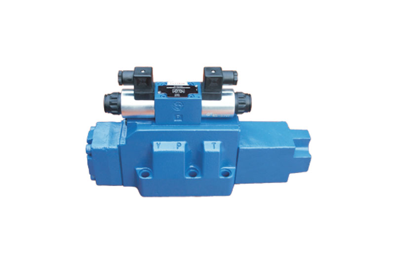
Figure 4. Hengli NG32 valve (Courtesy of Hengli America)
With P and T on the left, fluid travels from the manifold up through all four valves and back down again. It can take some getting used to when valves are referenced both upwards and downwards. Any valve situated in the P or T lines will be directed upwards, but valves in the A and B work lines are drawn upside down.
When stack valves are made to flow more than a D05 (NG10) is capable, a pilot operated valve must be employed. An electrical solenoid’s power isn’t enough to overcome the flow forces inside a large valve, so the spool must be moved by hydraulic energy, like a small steel cylinder rod. The pilot valve is mounted atop the mainstage spool as shown in Figure 4, but the symbol can be drawn in two ways.
The first is the simplified version, Figure 5, the compound operator symbols show both pilot and solenoid operation, while the rest of the valve remains standard in its description of a 4/3 spring-centered valve. When you look at the expanded symbol below it, two valves are more accurately describing what is seen inside the valve.
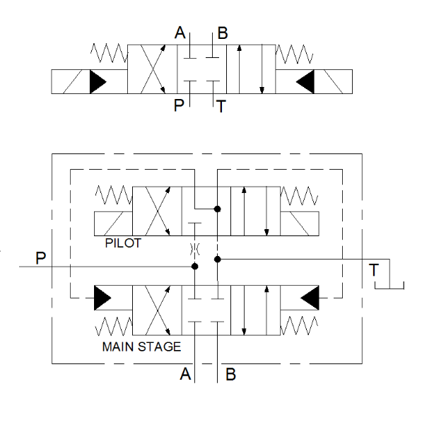
Figure 5. Pilot-operated valve
A single pressure line enters the valve where it feeds both the pilot and the mainstage valve. Because this example has an internal pilot supply, it also has an orifice to limit flow entering the pilot valve. Without an orifice, the valve would be exposed to potentially hundreds of gpm when it was designed to handle just a few. The pilot valve is solenoid operated, and when shifted, sends pressurized fluid to the main stage spool, shifting it easily.
Both the main stage and pilot valve drain through a common tank line, in this case. However, just as pilot energy can be via external supply, so too can the pilot valve drain externally. This is always a good idea when backpressure in the primary return line becomes too high, which may affect the pilot valve performance. In the next article of the series, I’ll discuss pressure valve basics and the various ways they’re drawn.
Filed Under: Fluid Power Basics