
By Jeremy Beale
In our editorial series covering designs for power-limiting, open-circuit architectures, we first covered high-low cylinder applications and flow-amplification concepts. Let’s now turn to regeneration. For cylinders with small rod diameters, the flow rates on either side of the cylinder are similar. It would then be more practical to use a “regenerative” approach, transferring fluid directly from one side of the cylinder to the other, rather than returning to tank.
This is done via Unit 4 as shown in the circuit diagram below. Unit 4 would be sized as closely as possible to the desired rod-side flow rate. Unit 3 would then be sized to provide the “missing” bore-side flow due to cylinder area ratio.

Regenerative flow-divider concept
There are several benefits from this approach:
a. For a relatively small rod, Unit 3’s size will be only a fraction of Unit 4’s size. This decreases the cost of the overall system.
b. Large reservoir connections are not needed, because the majority of flow now passes through Unit 4 without returning to reservoir.
c. Eliminating large tank connections simplifies construction of the system and will reduce turbulence and churning in the reservoir. The overall reservoir size can therefore decrease substantially.
d. Although Unit 4 handles the majority of flow in the system, it is still somewhat smaller than Unit 4 from the flow-divider circuits previously discussed in “Flow amplification limits valve losses.” Unlike in those circuits, Unit 4 is no longer responsible for transferring all the fluid for the cylinder’s bore end.
e. Less heat is generated compared to the previous flow-divider circuits, due to downsizing of various components.
There is at least one disadvantage to this approach. Because Unit 4 does not draw directly from the reservoir, it will be “dry” on startup. No oil would initially be available to either of Unit 4’s ports, causing a potential cavitation hazard. The solution is using the existing valves to fill the cylinder and lines before Units 2, 3 and 4 are engaged. Specifically, the operator should cycle the cylinder several times via the 4-way high-pressure work valve.
Ultimately the various downsizing advantages make this “regenerative” design the optimal choice for nearly all “flow amplification” applications, regardless of rod diameter.
Depending on the choice of gear/vane/screw or other type device for Unit 4, it may be impractical to have Units 2, 3 and 4 series-mounted as shown in the previous diagram. As an alternative shown in the circuit below, Unit 3 is split off with a separate hydraulic motor, Unit 5.
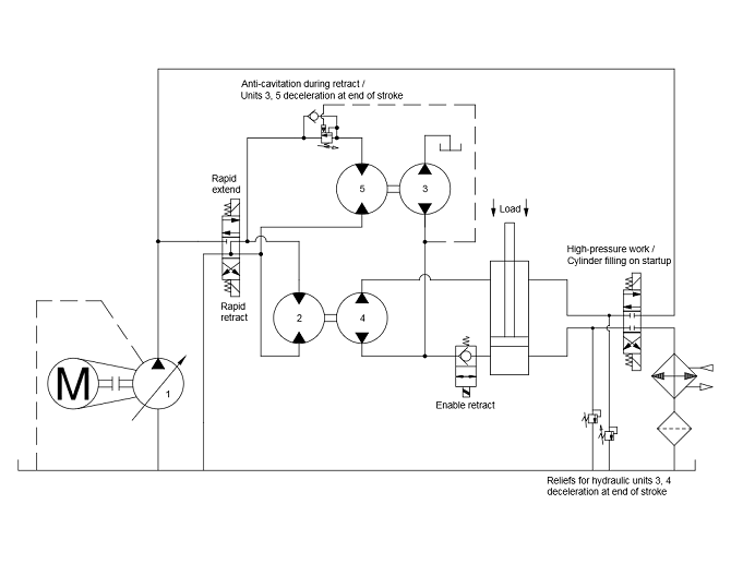
Regenerative split flow-divider concept
The downside of this design is obvious: added cost of a second, smaller hydraulic motor (Unit 5). Also, a counterbalance valve is needed to regulate Unit 5.
However there are several benefits:
a. Unit 3 is no longer forced to turn at the same speed as Unit 4. This freedom of motion allows Unit 3 to “adapt” to the instantaneous flow requirements:
• During extension, Unit 3 will accelerate until pressure builds in the cylinder bore end (or pressure builds due to the overspeed limit of the flow control). Constant speed is reached when bore-end pressure balances the torque on Unit 5 created by pressure from Unit 1.
• During retraction, Unit 3 will accelerate until pressure is lost in the cylinder bore end. This loss of pressure will cause the counterbalance valve to modulate, thereby preventing cavitation in the cylinder bore.
b. These “adaptive” benefits let engineers eliminate several valves from the series-mounted split flow-divider design. The now-unnecessary valves are the anti-cavitation checks and the rod-side dump solenoid valve.
c. The counterbalance valve will also serve to decelerate Units 3 and 5 at the end of each retraction stroke.
d. The physical location of Units 3/5 and Units 2/4 can now be optimized. Units 2/4 should be as close to the cylinder as possible, to minimize the plumbing length of the large lines attached to Unit 4. Conversely, Units 3/5 should be as close to the reservoir as possible, to improve the suction characteristics of Unit 3.
Note that overall power consumption should be nearly identical to the series-mounted regenerative design shown in the second circuit. The sizes of Unit 3 and Unit 4 are unchanged. The size of Unit 2 can be reduced, because Unit 5 now provides torque for Unit 3. There will be some minor losses from the counterbalance and flow control valves for Unit 5.
Unit 5 should be slightly oversized relative to the expected torque requirement for Unit 3. This oversizing ensures rapid response from Unit 3, thereby preventing Unit 3 from “lagging” Unit 4 in terms of dynamic response. That’s important because permitting the speed of Unit 3 to “lag” Unit 4 during extension would cause cavitation in the cylinder rod end. Note that there are other approaches for synchronizing the rotation of Unit 5 and Unit 2. For example, these motors could be connected in series rather than in the parallel circuit shown.
To see previous installments in this hydraulic design article series, visit:
Design concepts for open-circuit architectures
Flow amplification limits valve losses
Filed Under: Cylinders & Actuators, News, Pumps & Motors