
By Jeremy Beale
One hydraulic design approach that can be used to minimize valve size/losses is to incorporate opposite-phased cylinders into an application. It is most suitable under the following conditions:
1. Pressure and flow requirements match “high-low” operations. Here cylinder motion involves a low-pressure, high-flow stage; and a second a high-pressure, low-flow stage. A typical example is the compacting cylinder on a refuse truck. As the cylinder extends, pressure slowly builds due to the elastic nature of the material. Pressure increases rapidly towards the end of stroke. Then the cylinder retracts quickly under negligible load.
2. High-volume production environments with many identical hydraulic presses operating in parallel. Typical industry examples would be plastic extrusion or recycling centers.
3. Cylinders with oversized rods. This is already required for many long-stroke devices for column strength support.
The approach involves connecting a second cylinder/hydraulic press at opposite phase from the first press. This method is more precise than the flow-divider approach, where a “step-down” transformer uses energy from the high-pressure stream to generate low-pressure streams at higher flow rates. Both cylinders can be identical, such that flows entering and exiting are identical. The operating principle is shown below. Hypothetical pressures provide context.
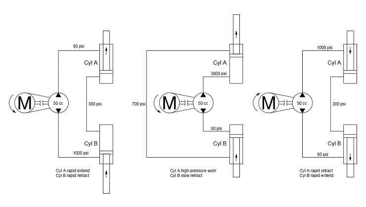
Opposite-phased cylinders operating principle
When rapid motion is desired, a pump would ideally connect the rod ends of both cylinders. The bore ends would exchange flow freely. When high pressure work is desired, the pump would ideally connect the bore ends, while the rod ends exchange flow freely. To make best use of the concept, oversized cylinder rods should be used. The area ratio of each cylinder will provide flow amplification for rapid motion.
Note that although not examined further, the closed-circuit concept shown above could be implemented with a single 6-way valve to “switch” a closed-circuit pump between the two positions. Another closed-circuit design could involve separate pump + motor groups in the two positions. A single VFD would alternate between the two. Lastly there would be a large 2-way valve between the cylinder bore ends. This valve would open to facilitate rapid cylinder motion.
Obviously it is not possible to freely connect and disconnect a pump in the ideal case above. Valve connections are the solution. For the open-circuit case shown below, two 4-way valves are used.

Hydraulic press concept
Rapid motion occurs by energizing the rod-side 4-way valve along with the bore-side 2-way valve. High-pressure work occurs by energizing only the bore-side 4-way valve. After each working cycle, the cylinders should be “re-phased” to ensure completed strokes on each motion. This “re-phasing” is done by fully retracting one cylinder, while fully extending the other. Specifically, energize opposite coils of both 4-way directional valves while leaving the 2-way valve closed.
This design introduces a few problems, which are addressed in the more-detailed circuit shown in the graphic, “Hydraulic press using opposite-phased cylinders.” Specifically:
a. Pressure intensification is always a potential hazard with oversized-rod cylinders. Relief valves are necessary under the “A/B Rapid Travel” valve.
b. For maintenance reasons, it is helpful to move either cylinder independently. In the above circuit, it is possible to extend either cylinder independently by energizing symmetric coils of both 4-way valves. The selected cylinder will experience full pump pressure on both sides. It will then move due to differential area. However it is not possible to retract either cylinder independently. This would require additional bore-side dump valves which are not shown in the graphic below.
c. The “Rapid motion enable” 2-way valve must be oversized to minimize throttling losses. This is especially important because minimal cooling is available for the oil trapped between the two cylinders. Specifically, a small amount of cool oil will be introduced each time the high-pressure work valve is energized.

Hydraulic press using opposite-phased cylinders
Note that the heat exchanger is shown receiving flow from the rapid travel 4-way valve. This is a simplification for convenience. Other return lines can also be fed to the heat exchanger:
Several benefits of this design include:
a. High-low type operation is achieved with minimal flow passing through the 4-way directional valves. The largest flow will only need to pass through the “Rapid motion enable” 2-way valve, which can be suitably oversized.
b. A single hydraulic unit can operate two hydraulic presses. From an economic perspective, mass-production situations often involve many presses operating in parallel to achieve production volume. This design can cut the total number of hydraulic units by half.
c. The physical footprint of the unit is smaller than a traditional high-low design.
d. The “Rapid motion enable” valve can potentially function as a decompression valve. When switching from extension to retraction, energizing this valve will allow Cyl A to decompress into Cyl B or vice-versa. If this decompression is too sudden, a smaller 2-way valve can be added in parallel with the existing 2-way valve.
Several downsides include:
a. Initial higher cost of cylinders with oversized rods. However oversized rods are already necessary for applications with long-stroke cylinders due to column strength requirements.
b. The “Rapid motion enable” 2-way valve must be oversized to avoid throttling losses at high flow rates.
c. Hydraulic maintenance will take two presses offline rather than one.
If independent retraction is desired for maintenance reasons, an additional 3-way valve is needed. This valve would vent the bore side of either cylinder to tank. At the same time, the “rapid extend” 4-way valve would pressurize the rod side of the same cylinder to retract it. Repeat the process to retract the other cylinder.
Depending on working cycle frequency, an accumulator could be installed at the pump outlet to reduce pump/motor size.
To read previous installments in this hydraulic-design series, see:
Design concepts for open-circuit architectures
Flow amplification limits valve losses
Regenerative concepts for flow amplification
Filed Under: Cylinders & Actuators, News