
By Jeremy Beale
In our series on design concepts for limiting power losses in hydraulic circuits we’ve looked at various applications. These include “high-low” cylinders, displacement-controlled actuators, flow amplification, regeneration and opposite-phased cylinders. Now let’s delve into the use of hydraulic motor two-speed drives.
Consider the following load-sensing hydraulic circuit:
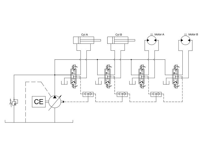
Generic load-sensing circuit
Suppose that one of the four actuators should require an intermittent high-flow, low-pressure condition, which the current system cannot provide. The system designer must now decide from several upsizing options:
a. Increase pump size. As a consequence, reservoir size must increase. The combustion engine may need to be upsized, depending on the pump control scheme. The valve supplying the high-flow actuator must be upsized to handle the extra flow. A larger pump will generate more heat throughout the cycle, possibly requiring a larger heat exchanger.
b. Add an accumulator to the pump outlet. The valve supplying the high-flow actuator must be upsized to handle the extra flow. Depending on how frequently it is used, the accumulator will contribute significantly to additional system heat, requiring a larger heat exchanger.
c. If the high-flow actuator is one of the two cylinders, a regenerative valve assembly (such as the Sun Hydraulics YDCCLHNAK) could be used to improve extension speed. Heat concerns will depend on valve sizing. Retraction speed is not improved.
d. If the high-flow actuator is one of the two cylinders, the best option would be to apply the approached discussed previously in “Regenerative concepts for flow amplification.”
If the high-flow actuator is one of the two hydraulic motors, then a new circuit is required. Conceptually, it is similar to the regenerative flow-divider concept, with a few modifications.
a. The flow imbalance of a cylinder does not exist for a hydraulic motor. This means the flow divider can consist of only two sections rather than three sections.
b. Because a third flow divider section is not used, there is minimal flow being exchanged to/from the reservoir. While a small portion of the flow may pass through case drains, the vast majority of the system flow will circulate continuously in a closed loop between flow divider and hydraulic motor. This recirculation may create an overheating risk, depending on the working cycle. More flow should be exchanged with the reservoir via a hot-oil shuttle valve. The shuttle valve flow rate can be increased with “flushing” pressure supplied through the make-up check valves.
c. Cross-port relief valves are required to prevent hydraulic shock from rapid load deceleration and acceleration.
d. High-pressure can only be applied to Unit 5 if a brake keeps Unit 4 stationary.
The following circuit incorporates the suggested changes. It omits the load-sense capability of the original 4-actuator circuit for simplicity. Also only one actuator is shown. The remaining three (or any number of) actuators would be connected in parallel.
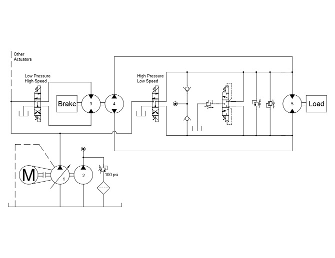
Hydraulic motor two-speed drive
When possible, this circuit can be avoided by converting the hydraulic motor (Unit 5) to a variable-displacement version. Reduced motor displacement would then provide higher speed. However a variable-displacement motor is not always possible or practical, especially for large radial-piston units.
Note that isolation valves may be required for Unit 4, depending on whether it can withstand the high pressures applied to Unit 5 during that part of the operating cycle. If isolation valves are installed, no brake is needed for the Unit 3/4 assembly. However cost and throttling loss concerns may lead the designer to simply select a different type of hydraulic unit for Unit 4 — one rated for high pressure.
To read previous installments in this hydraulic-design series, see:
Design concepts for open-circuit architectures
Flow amplification limits valve losses
Regenerative concepts for flow amplification
What are opposite-phased cylinders?
Filed Under: Cylinders & Actuators, News, Pumps & Motors